
- About the Journal
- Editorial Board
- Review Process
- Author Guidelines
- Article Processing Charges
- Special Issues
- Current Issue
- Past Issue
 Current Research in Materials Chemistry
Current Research in Materials Chemistry Volume 1 (2019), Article ID: CRMC-106
https://doi.org/10.33790/crmc1100106Review Article
How to Develop and Present a Concept Apparatus to British Petroleum as a Template to be Structured and Mechanized in Stopping the Gulf of Mexico Oil Spill in the Year 2010
Julius L. Harp
1Department of Chemistry, North Carolina Agricultural and Technical State University, 1601 East Market Street, Greensboro, NC 27411, USA.
Corresponding Author Details: Julius L. Harp, Department of Chemistry, North Carolina Agricultural and Technical State University, 1601 East Market Street, Greensboro, NC 27411, USA. E-mail: harpj@ncat.edu
Received date: 27th November, 2019
Accepted date: 24th December, 2019
Published date: 27th December, 2019
Citation: Harp JL (2019) How to Develop and Present a Concept Apparatus to British Petroleum as a Template to be Structured and Mechanized in Stopping the Gulf of Mexico Oil Spill in the Year 2010. Cur Res Mater Chem 1: 106.
Copyright:©2019, This is an open-access article distributed under the terms of the Creative Commons Attribution License 4.0, which permits unrestricted use, distribution, and reproduction in any medium, provided the original author and source are credited.Creative Commons Attribution License, which permits unrestricted use, distribution, and reproduction in any medium, provided the original author and source are credited
Abstract
In this paper, I have strategically developed a variety of conceptual methods that were to be used in constructing conjugates or supporting apparatuses which then would serve as incorporates to assist in building components that are expected to give rise to a universal conceptual apparatus. This universal conceptual apparatus was to serve as the main template for further applicational designs in bringing the catastrophic flow of oil involving British Petroleum’s Deepwater Horizon in the Gulf of Mexico to a complete halt during the year of 2010. The supporting apparatuses were structured with features that delineated a systematic and comprehensive approach toward clarifying the utilities of the universal conceptual apparatus. The universal conceptual apparatus can be defined as a multifunctional concept unit, and it was designed to serve as a convenient template used to construct an applied apparatus that was geared to stop the Gulf of Mexico oil spill. Many obstacles were anticipated throughout the endeavors pertaining to the development of the universal conceptual apparatus. The challenges presented by the underwater environment of the Gulf of Mexico was at the edge of human technology. In addition, there were no ideal templates available to serve as references in constructing an oil stoppage apparatus to be effectively applied toward a never-before sea level task. Throughout this critical period of time, there were informational delivery challenges; which included the development of successful strategies required to get the conceptual technologies to the appropriate national emergency or security units within the United States of America. The need to establish a resolution of this environmental disaster had reached a critical threshold as it progressed toward, the destruction of a multitude of lifeforms in its path, the potential development of cataclysmic tsunamis as well as the demise of devastating the US economy.
Keywords: Multi-functional dual capping chamber; Docking space; Mechanical contracting devise; Tri-stacking/capping valves; Capping stack; Bounce-back/Dampening/Springing pressure effect
Introduction
On Tuesday of April 20, 2010, an offshore oil rig belonging to British Petroleum (BP) exploded in the Gulf of Mexico, killing 11 workers, injuring 17 others, and spilling approximately 205.8 million gallons of crude oil [1]. In addition, 1.8 million gallons of toxic chemical dispersants were used in response to this catastrophe. British Petroleum’s Deepwater Horizon oil spill had spread roughly 130 miles long and 70 miles wide; impacting Louisiana, Mississippi, Alabama and Florida. The release of oil continued for 87 days (i.e., nearly 3 months) while devastating the natural habitats of a variety of aquatic species, this included many endangered species [2-4]. The Gulf of Mexico Oil Spill turned out to be the worst unintentional [5] oil spill on planet earth and was on the verge of permanently devastating the US economy. Out of a crew of 126 on the Deepwater Horizon drilling platform, 98 individuals were fortunate to have escaped injuries from this death-defying disaster. This disaster occurred one mile below the upper sea-level, and the piping construction went down two additional miles. These sub-sea level depths, created never-before environments; which in term would require the resolutions of neverbefore problems. From April 20, 2010 until current, the fallout of this catastrophic event is still being measured as related to the health effects on many of the Gulf Coast residents, and overall impacts on the ecological and economic structure of the affected areas [2-4]. This unfortunate moment in America’s history was not voided of appropriate responses from the elitist of national and international experts [6] in directing their collective know-how in attempting to halt the flow of oil into the Gulf of Mexico. In this effort to prevent the flow of oil into the Gulf of Mexico, several strategic efforts were attempted [7,8]. During the interim of this catastrophe, it was presumably safe to say that President Obama was at his highest stage of concern regarding America’s securities [4,9]. An unresolved question pertaining to this cataclysmic mishap is still being raised as to, “how long could the oil spillage had continued in the Gulf of Mexico if all measures had failed regarding this endeavor”? There are still unsettled debates related to the actual date that the final oil drop ceased within the confine of the Deepwater Horizon oil well [10,11]. On Saturday, July 15, 2010, it was announced that the Deepwater Horizon oil spill had finally come to a comfortably end [12,13]. During the interim of the oil spill crisis and currently, the US and BP will continue to plan and implement restorations measures pertaining to the Gulf disaster [14,15].
Within two weeks of great concerns following the on-set of the Gulf’s oil spillage, this calamitous mishap spearheaded actions from one of many concerned Americans to develop a multifunctional concept apparatus geared to stopping the Gulf of Mexico oil spill.
As a result of this never-before calamity, no specific templates were available for conveniently constructing apparatuses in stopping the Gulf oil spillage. During the interim of the oil spill, proper protocols suggested that President Obama be reached in order to let him know of the inventor’s plan to construct a never before apparatus to be used in stopping the flow of oil in the Gulf of Mexico in the year 2010. In addition, it was practical to contact one of the most knowledgeable oceanographers, Dr. Jerome Milgram [16,17], an Ocean Engineering Professor at the Massachusetts Institute of Technology in Cambridge, Mass and who would offer some insight as to how the Gulf of Mexico oil spill compared to other cataclysmic oil spills, and their final outcomes based on the stoppage methods used. Regardless of the red tape and bureaucracy expected throughout this calamity, it was highly critical to devise a variety of strategic plans for successfully delivering pictorial templates to BP for constructing plausible apparatuses in stopping the Gulf of Mexico oil spill. In this endeavor, it was necessary to establish a systematic approach that would consist of, contacting the Oval Office in the USA, establishing alliances with reputable experts in appropriate fields of studies (e.g., physic) such as oil-oceanography and flow dynamics, contacting local government offices that could serve as pathways to other governmental emergency agencies, and contacting BP directly.
The most important aspect of the inventor’s research focus was to facilitate the construction of conceptual apparatuses which displayed workable applications that would be turned over to appropriate experts; who would then expand the templates into a multi-functional apparatus that would resolve the Gulf of Mexico Oil Spill. In the development of the concept apparatus, a sequence of strategic constructions were theorized and then developed pictorially to serve as follow, Reconstruction of the leaking oil wellhead pipe to allow for easy connection to an upper pipe system; Structure the upper pipe system with venting units to off-set the high oil pressure coming from the leaking oil wellhead pipe upon both units being connected; The aforementioned upper pipe system is to be mechanized at its connecting end by-way of anti-locking/adhering/ or bolting (i.e., preconfiguring) unto the leaking oil wellhead pipe to give rise to a unified pipe system which could be framed to be detachable; The top portion of the unified pipe system is prefigured to adapt to any connective system in order to allow options for a plethora of desired functions, including a connective hose to lead the oil to the surface to be collected into an oil tanker above the sea; The inside of the top portion of the unified pipe system is to be designed with strategic protrusions that pulverize solid methane particles floating in the oil by acting as an anti-clogging component; The inside of the outer connecting pipe system (i.e., outer capping chamber) is to be encapsulate and unify onto the inner pipe unit such that the outer capping chamber is to regulate the temperature of the inner pipe unit to prevent large chunks of solid methane formation within the flowing oil.
Experimental Setups, Results and Discussion
In this work, several capping chamber components will be theoretically constructed and pictorially/ conceptually presented such that qualified experts can then expand on the templates to derive a multi-functional apparatus that is to be used favorably in terminating the Gulf of Mexico Oil Spill. In Figure 1, a structural extract of the dual capping chamber (DCC) is given in order to visually isolate and to focus important mechanistic features of “the principal concept apparatus”. A key step in docking or lowering the DCC onto the high-pressured pipeline wellhead (PL/WH) a, is the utilization of the mechanical contracting devise b/b’ used to reconstruct the PL/WH such that an optimum and secured fitting connection is established between the PL/WH and the inner chamber c of the DCC. Thus; as demonstrated in Figure 1, docking take place such that the inner chamber c of the DCC is secured “into” the PL/WH. Alternatively, docking can take place such that the outer chamber d of the DCC is secured “onto” the PL/WH. During either docking step or pipe to pipe unification step, it is essential to open the pressure releasing vents e in order to counter the pressure of the gushing oil mixture at point a. In the process of docking, the shape of the lower portion of the DCC is configured to be self-seeking or to be perfectly centralized when lowered onto the connecting PL/WH. As the pipes are being unified, the flexible and durable anti-locking prongs f are being reversibly locked into the PL/WH by the sheer weight of the downward force of the dual capping chamber. The flexibility and durability of the anti-locking prongs f; as well as other features associated with the development of the DCC are to be facilitated by the use of smart materials. Smart materials can be tailored with properties that are favorably responsive to external conditions such as temperature, light, pressure, electricity, voltage, pH, or chemical compounds [18]. As the oil containing solid methane is flowing through the inner chamber c, the surface protrusions g is designed to pulverize larger chunks of solid methane that are flowing in the gushing oil. The construction of the surface protrusions g involves particular angle designs in order to offset pressure buildup and to maximize shearing effectiveness on clumps of solid methane; while ultimately allowing for smooth oil flow, anti-clogging. The maximized shearing effectiveness of the surface protrusions g on the clumps of solid methane is inclusively influenced by enhanced surface contact between the flowing solid methane onto the surface protrusions g. The outer chamber d is designed to be separate but inclusive with the inner chamber c and can serve as a versatile nonflammable heating unit that assist as a temperature regulator of the inner chamber c; such that the methane is gasified and portioned off in its upward travel within the inner chamber c. An example of the outer chamber d serving as a versatile nonflammable heating source/reservoir, is the use of heated water or an aqueous-antifreeze mixture flowing within the outer chamber d and simultaneously insulating the temperature onto the inner chamber unit c to prevent solid methane formation within the inner piping chamber, anti-clogging of solid methane.
Figure 2 represents a continuation of Figure 1, and focus attention on some additional mechanisms of pipe docking and sealing. Before this alternate capping chamber method can take place, a few precursory mechanistic steps are required for preparative use of the apparatus. As mentioned previously, the inner chamber c of the weighty dual capping chamber is docked into (e.g., or onto) the PL/WH a by utilizing the oil pressure off-setting vent e. Upon pipe unification of the DCC into PL/WH, high pressure is vented in at h and exited at i in order to overcome the sea upward flow-pressure into the outer chamber d. It is at this point and condition that an appropriate sealant can be added through the ports at j since the capping chamber now has a positive outward pressure at point i; no sea water can back up into the chamber d provided that all other appropriate systems are closed or properly regulated. The added sealant through port j is to flow out of the outer chamber unto the outer surfaces of both the inner chamber and the PL/WH; thereby giving rise to pipe-to pipe unification within a water-free environment. This water-free environment is to suggest that a lit match can maintain a flame above point h, provided that all other relevant systems are closed or properly regulated. It is important that the sealant accumulation is regulated for proper buildup at the interphase between the PL/WH and inner chamber of the DCC or capping stack. It is also critical that the sealant material has the proper smart properties such as selective chemical dissolvability; which allows for pipe-to pipe dysconnectivity. Please note that the DCC is fitted with retractable pressure barriers k to prevent sea-ground displacement cause by the exiting pressure at point i which could potentially weaken the support structure of the earth around the PL/WH, and could affect essential visibility when required. At points, l of the DCC, there are three shutoff valves (i.e., tri-stacks) which allow for selective flow diameter(s) or volume(s), and where the valves arrangement has the propensity to reduce the initial oil and continued oil pressures within the inner chamber of the DCC. Therefore, the proper timing and sequence of flow space or volume (i.e., opening/closing) control is pivotal in maintaining the integrity of the entire piping system, both under the sea-ground and above the sea-ground. The tri-stacking valves can be equated as having three pipes securely connected to each other, and their inner diameters are allowed to be regulated so as to influence the flow rate and pressure of the unified apparatus. The most important aspect of the tri-stacking valves is their ability to shut-in, or shut off the oil flow within the apparatus to be used in preventing the flow of oil in the Gulf of Mexico. Area X is located within the top portion of the detachable DCC and has the versatility of being preconfigured such that it can be supportive and complimentary to a plethora of desired attachments. For example, if the Gulf of Mexico oil well is unable to be shut off, then the tri-stacking valves can remain opened at the optimal piping-spaces/inner-volumes diameters, and whereas a hose can then be perfectly attached to preconfigured Area X to be led to the surface for oil tanker collection until a better stoppage plan is developed. If necessary, all components associated with the construction of the DCC can be designed as retractable units.
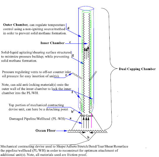
Figure. 1 Base diagram of multi-functional dual capping chamber with smart operational capabilities

Figure. 2 A continuation of Figure. 1 transitional diagram of multi-functional dual capping chamber.
Figure 3 is essentially designed as a self-explainable dissect or extract of “the principal DCC” that displays an endo pipe-to pipe connecting (ENPPC) into the PL/WH, and is used to highlight the mechanisms of piping unification or piping docking. Endo pipe connecting involves the inner chamber of the DCC being inserted into/inside the PL/WH (Figures 3). Note, in Figures 1-3, the mechanism of piping unification is displayed as ENPPC. Alternatively, piping unification can be mechanized to undergo exo pipe-to pipe connecting (EXPPC) or docking if necessary. Exo-connecting involves the inner chamber of the DCC being connected over/onto the PL/WH. There is a third method of piping unification to be termed as direct pipe-to pipe connecting (DPPC) which might involve the pre-configuration of the top portion of the PL/WH or top pipe unit to be screwed or fastened in a flush manner onto an additional specialized piping unit. Preconfiguration of the PL/WH is to be accomplished by utilize all of the applications of the mechanical contracting devise as conveyed by unit b and b’ in Figures 1 and 2. Direct pipe-to pipe connecting is more clearly implicate in Figure 2 within the domain of Area X, and will be thoroughly demonstrated later in this work. Another important aspect of all pipe-to pipe connecting, is to reserve various option for disconnecting/de-docking of piping units, either through chemical or physical means. Other appropriate cases of pipe-to pipe disconnection might require the use of smart materials. For example, to employ materials at the connective junctions of the piping units that will timely expand due to the entry frictional force caused by pipe-to pipe connecting or by pipe unit(s) connecting to the PL/WH. At an appropriate time later, this material can be chemo-selectively dissolved from the pipe-to pipe connection, or chemo-treated to allow for the smart material to undergo shrinkage when the docking unit is pulled out in the opposite direction. Figure 3 displays a reverse or anti-locking mechanism as exemplified at point f in Figure 1.
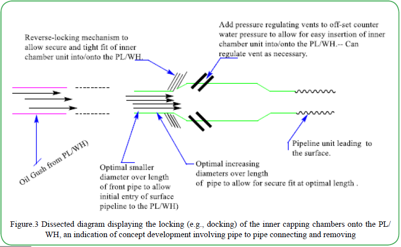
Figure. 3 Dissected diagram displaying the locking (e.g., docking) of the inner capping chambers onto the PL/ WH, an indication of concept development involving pipe to pipe connecting and removing
The key focal points to be emphasized in Scheme-1 are directed toward understanding the mechanism of exo pipe-to pipe connecting (EXPPC) or docking by utilizing the apparatus given in the reference insert (i.e., excluding PL/WH) to be understood as the base unit. Note that the reference base unit consist of vents that are to be in the open position to allow for assured docking onto the PL/WH without being blown-off by the pressure of the gushing oil. Sequentially, a high positive pressure will be generated in front of the sealant feed-lines so that sealant will be allowed to flow (i.e., casted) uninterrupted onto the outer surface of the PL/WH to produce unification, an assured adhesion. In the next step of this process, the dialing levels of the three shut-off valves associated with the reference base unit can be set to influence various flow diameters that can mimic the three conical diameters of the tri-construct in case 1 or case 1’, following Step-4 in Scheme 1. Thus, if the shut off valves of the reference base unit displayed the sequence of, valve-1 being most opened when compare to valve-2 and having valve-3 being completely closed, then the reference base unit would exhibit the same effect as the final tri-construct of case 1 in Step-4; where the oil flow would be completely stopped. Alternatively, if the shut-off valves produced a gradient shutdown where, valve-1 was more opened that valve-2 and valve-2 was more opened than valve-3, then the reference base unit would exhibit the same effect as the final tri-construct of case 1’ in Step-4. In the aforesaid scenario where pipe-3’involving case 1’ is fitted with a hose, the oil can be led through the hose to the surface and collected into an oil tanker.
In clarifying the entire process of option 1 in Scheme 1, Pipe-1 is to be consisted of all appendages as those referenced in the base unit (minus the shut-off valves). Thus, in adhering pipe-1 onto the PL/WH, pipe-1 is vented, docked, and sealed onto the PL/WH to produce unification. In Step-3, Pipe-2 undergoes venting, docking and sealed onto Pipe-1 to produce unification. In Step-4 involving the culmination of Pipe-3 or Pipe-3’ (e.g., parallels the reference base unit) containing the three shut-off valves undergoes the same process as in Step-3 such that the shut-off valves become the major controlling factors in regulating a plethora of variables within the arena of flow dynamics. The aforementioned steps are to give rise to the apparatus in case-1, or with the option of giving rise to the apparatus in case-1’. In Steps-1-3 where the conical ends are open (i.e., shutdown/off valves 1-2 are open), this scenario specifically implies that when the conical ends are in the opened positions, the pipe-1 to pipe-2 systems can be docked onto each other without being ejected by the high pressure of the gushing oil. In coupling this opened conical pipe-pipe construction effect to the apparatus venting influence, an emphatic counter pressure reduction is to be expected. As long as all conical ends of the unified piping system are opened, the last pipe unit (e.g., pipe-3) can be pre-fitted with a hose to lead the oil to the surface and collected into a tanker. It is important to note that valves dialing or valves opening/closing correlates to the variable internal diameters (VID) of pipes, and the VID of pipes can be optimally adjusted to allow flow pressure within the inner piping to be regulated to the near point of drastically lowering the oil flow without using the final shut-off valves. Thus, the number of conical pipes units, their inner diameters (i.e., shapes), and the various pipes arrangements will play important roles in regulating all flow variables that directly impact the integrity of the integrated DCC system, above sea-ground and below sea-ground.
In constructing an optimal conical devise used to stop the Gulf of Mexico and related oil spills, it is suggested to start with a completed, pre-constructed devise such as in case-1’. Thus, there would be no need to seal pipes onto one another; such that all three cones are initially associated with the single pipe unit as in case-1’. An important aspect in upgrading the design of the pre-constructed conical devise as in case-1’, would be the mechanization of the three internal cones formations which allows for the real-time control of cones diameters as needed. In consolidating the analysis of Scheme 1, the three shut-off valves pertaining to the base unit are analogous in their influence when compared to the three conical openings of the apparatus represented as case-1’. A more creative design of the DCC apparatus would involve coupling of the tri-conical flow reductive/regulatory apparatus in case-1’(i.e., at the end of pipe- 3’) to an optimal length hose containing multiple shut-off valves. This arrangement would initiate a gradual flow reduction occurring throughout each conical length-point which can then be followed by several gradual flow reductive points associated with each shut-off valve being regulated.
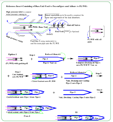
Scheme-1. Mechanistic procedure indicating dry casting under water, a concept development involving exo-pipe to pipe connecting and transitional piping unification displaying conical pipe closing.
The most important aspect to keep in mind when analyzing option-2 and option-3 in Scheme 2 is to realize that the concepts are identical to those of Scheme 1. In option-1 of Scheme 1, the base unit is representative of the tri-conical case 1’ construct; which allows Pipe- 3’ to be connected to a hose consisting of three shutdown valves. This resultant base unit would consist of three conical flow-resistant junctions/barriers (i.e., as in case 1’) and three flow-regulating valves, a total of six flow-resistant barriers that theoretically relate to six shutdown valves. In summary, the six shutdown locations of the proposed resultant base unit occur at the three curved interfering ends of each cone closures within their inner diameters, and the other three shutdown barriers consist of the optional three shut- off/shutdown valves coupled to the hose unit that is assumed to be connected to pipe-3’. When evaluating the final construct of option-2 in Scheme 2, pipe-1 has one curved conical flow resistant point and is proposed to have a hose with three shut-off valves. Thus, the final apparatus formed in option-2 of Scheme 2 is equipped with four shutdown regulators. The four shutdown regulators in option-2 of Scheme 2 are to consist of one flow restricting element at the cone end and the three proposed shut-off valves. There are five shut-off/down barriers involving the final construct of option-3 in Scheme 2 which include two curved interfering ends relating to the two cones closures and the three proposed shut-off valves. In the final analysis, each conical end is considered to be an obstruction point, or shutdown valve or a shut-off valve. An important aspect to note is that the base unit or last conical end connected to the hose and shutdown valves (i.e., regulating valves) is the pivotal flow controller.

Scheme-2. Mechanistic exo-pipe to pipe unification displaying conical pipe closing with hose connection leading to the surface to be collected in a tanker, or to undergo strategic boundary and midpoint flow control.
As aforesaid in the analyses of Figure 3, direct pipe-to pipe connecting (DPPC) was implicated in Figure 2 within the domain of Area X. Direct pipe-to pipe connecting could result from the pre-configuration of the PL/WH or any pipe unit in order to allow for a flush screwon entry onto another specialized piping unit as displayed in Step-3 of Scheme 3. Thus, direct pipe-to pipe connecting involves a flush connection between two pipe units without either of the pipes going into or over the other. Pre-configuration of the PL/WH, PL, WH, or of any other appropriate source unit is to be carried-out by all of the applications associated with the mechanical contracting/modifying devise displayed by unit b and b’ in Figure 1; 2. In the analysis of the apparatus displayed in Scheme-3 during Step-3 below, it is important to equate Pipe-1 as having all of the capabilities as displayed entirely with the apparatuses presented in Figures 1-3, mainly that Pipe-1 is a DCC consisting of a mechanical contracting/modifying devise and etc. In particularly, Pipe-1 has the capabilities of reshaping the PL/ WH for optimum adherence within/onto the docking domain of Pipe- 1. Pipe-1 in Scheme 3 (Step-1) is a preconfigured unit consisting of three female threaded groves with the capability of being most securely conjoined by two outside male screws associated with the preconfigured locking unit as displayed in Step-3 of Scheme 3. In addition, the pre-configured locking unit is equipped with regulating or shut-off valves that allow options to engage in synchronous or non synchronous closures procedures. Synchronous pipe(s) closure relates to a procedure of dialing the three shut-off valves simultaneously to the same level; which allows the oil to flow out of the preconfigured locking unit or outflow piping(s) with a straightline flow direction. Thus, synchronous pipe(s) closure is to give rise to linear pipe(s) flow dynamics. Non-synchronous pipe(s) closure relates to a procedure of dialing the three shut-off valves in an appropriate manners such that the valves come to rest at different levels to produce a half cone shape within the resulting volume shaft of the piping unit; which allows the oil to flow out of the preconfigured locking unit or outflow piping(s) in a downward or upward manner.

Scheme 3. Mechanistic exo-pipe to pipe unification displaying preconfiguration on pipe head with hose connection leading oil to the surface to be collected in a tanker, or to undergo strategic boundary and midpoint for flow control or stoppage.
Figure 4 is constructed to give a clearer understanding associated with many of the fluid-flow aspects pertaining to synchronous pipe(s) and non-synchronous pipe(s) closures procedures. Synchronous pipe(s) closure is exemplified under the heading of straight-line closure as illustrated in case-1. Synchronous pipe(s) closure is expected to give rise to linear pipe(s) flow dynamics. The ideal perspective of synchronous pipe(s) closure involves the synchronous regulation of all three shut-off valves concurrently from the same starting level and to come to a final dialing point displaying the same level; as can be referenced in case-1. Non-synchronous pipe(s) closure is illustrated under the headings of gradient closure as shown in cases 3-4. Non-synchronous pipe(s) closure is expected to give rise to non-linear pipe-volume filling(s) flow dynamics. Non-synchronous pipe(s) closure can involve synchronous dialing of all three shut-off valves concurrently as starting from different levels; such that the final dialing points of all three shut-off valves are to terminate at different levels (i.e., cases 3-4). Dialing or regulating the three shut-off valves in an advantageous manner under non-synchronous pipe(s) closure will give rise to a space-volume filling display that takes on the shape of a half-cone (i.e., cases 3-4). In the case of nonsynchronous pipe(s) closure, the half cone shape generated in the volume shaft of the piping unit is to produce an out-flow stream that can be directed downward or upward; whereas the upward flow is most preferred in terminating the oil-mixture flow (i.e., cases-3). When the half-cone volume filling display protocol is done correctly, the integrity of the entire piping system is expected to be optimally stable.
There are a variety of alternative valve shutdown/off procedures that are highly asymmetric; which generate chaotic flow dynamics that can destabilize the integrity of the entire pipping system, above sea ground and below sea ground. The optimal procedures for valves regulation during shutdown measures are expected to give a visual display of smooth volume flow; whereas the molecular forms within the stream of the oil mixture will act harmoniously in motion (i.e., collective molecular motion) throughout the fluid progression. These collective molecular forms within the fluid flow are to validate correct valves shutdown dialing as indicated by minimum initial fluidsplashing; this phenomenon is to be expected in cases 1;3. Case-2 displays a unique situation when it comes to the topics of gradient closure, straight-line closure, and fluid-splashing. For instance, the variation in the diameter at each conical outlet locations associated with the tri-conical closure prior to reaching the shut-off valves point, demonstrates a straight trajectory of variable widths of oil stream flow; where each variable transition originates at the three interactive junctions. Thus, it is important to note that a gradient point can be established at each adjacent outflow points of the conical unit in case- 2 as a result of unequal volume space/diameter between adjacent outflow points. The structuring of the conical closing apparatus in case-2 is proposed to establish an advantage in which the first outflow transitional volume/space is larger than the second, and the second is larger than the third, this is proposed to have a spring or dampening effect on internal pipe pressure. In this dampening effect, fluid-splashing is expected and the degree of splashing will need to be correlated with several physical variable within the pipe confined, including pressure. It is important to note that the piping units are not drawn to optimal scale. For example, the spacing between the conical outlet points or between the shut-off valves can be varied in order to determine or predetermine the optimal effective distance for appropriate oil-flow regulation. The optimal size/weight of the piping units and the optimal spacing between all interacting units are important factors in governing the overall integrity of the piping system, under the sea-ground and above the sea-ground.
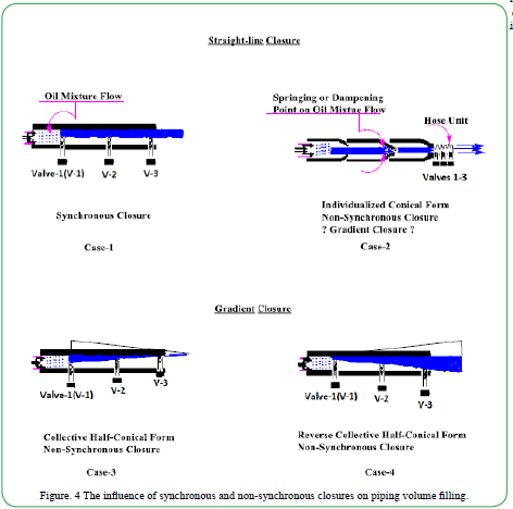
Figure. 4 The influence of synchronous and non-synchronous closures on piping volume filling.
Scheme 4 will be utilized to direct attention towards pipe-volume shaping/filling of liquid flow within various apparatuses and its influences on flow dynamics to ultimately be used in establishing valid concepts by comparing three aspects of piping closures or piping regulations. In this regard, outlet flow-points designs of piping systems will be assessed and compared based on their influences on linear pipe(s) flow and gradient pipe(s) flow dynamics. The resultant flow dynamic measurements associated with the influences of linear and gradient piping regulations are to be correlated with outcomes pertaining to system integrity and various pressure reading to name a few. In this investigation, Scheme 4 will be used to examine just three interaction points, cones and shut-off valves associated with each apparatus displayed. Example a1 will serve as a reference for constructing and analyzing the final apparatuses of the two “Bs” (i.e., b1; b2) series and the two “Cs” series given in Scheme 4. In using apparatus a1 as a reference, the final apparatuses pertaining to examples Bs; Cs are to be constructed by condensing the three pipes components displayed throughout casting episodes 1-3 to give rise to unionized or resultant apparatuses (i.e., as in a1 leading to episode 3’) consisting of three transitional volume points. In the analysis of the unionized apparatus in a1, the oil flow is to be directed through and unto three conical flow interactive sections as exemplified in the resultant unit, episode-3’. Each interactive sections of the tri-conical unit demonstrate three mitigation points of oil flow. In this process, the oil mixture originates from the PL/WH and transitions throughout pipes 1-2 and is ultimately shut-off/shut-in as a result of fluid volume-space (i.e., zero diameter) at the last conical interphasing piping construction, episode-3’.
In comparing a1 to a2, they both exhibit gradient flow dynamics as the oil flow volumes or spatial freedom fluctuate at all of the three interaction junctions throughout episodes 1-3. Thus, apparatuses a1 and a2 can both be classified as gradient flow closing apparatuses as indicated by the changing liquid volume-filling during each successive transitional flow points. In comparing a1 to a2, it is assumed that the conical shutdown sequence of oil flow to be exhibited in a1 will give rise to several advantages at the first two junctions, mainly the desired (i.e., optimal) pressure and flow preferences. For example, the oil flow shutdown sequence utilizing a unionized conical apparatus (i.e., resultant, episode 3’) as with a1 is expected to have the effect of lowering the forward pressure as a result of the smooth opposing bounce-back pressure (dampening) or springing effect on the fluid flow (i.e., see Figure 4, case-2). This apposing springing pressure effect is proposed to result from the smooth back splattering pressure which neutralizes the smooth forward pressure at the three transitional conical interaction junctions; while simultaneously the forwarding fluid at the outgoing side of the transitional interactive junction is free to flows unimpeded (i.e., Figure 4, Case-2). Note, this bounce-back pressure (dampening) or springing effect is not expected to occur within the regions of the three shutdown valves, this phenomenon gives preference to cone closure over valve closure. This dampening process is explicitly demonstrated in episodes1-2 regarding examples a1, and the c series in episodes1-2 (Scheme 4). This same springing effect is entirely operational throughout episodes1-3 in regard to the b series apparatuses (Scheme 4). Note, that both apparatuses in a1 and a2 represent complete shutdown protocols. In order to validation the aforementioned pressure dampening rationale, the optimal piping diameters and the cylindrical free flow-space arrangements of all conical closing junctions of the unionized apparatuses (a1, Bs; Cs in episodes-3) will need to be determined and correlated with the measured pressure outcomes. These pressure measurements are expected to establish universal profiles based on the deliberate constructs of the various apparatuses (e.g., As, Bs; Cs in episodes-3), and particularly at each interaction junctions. For example, a1 has a reducing volume gradient design at the transitional junctions (i.e., from episodes 1-2), and a shut-off/shut-in design at episode 3. In regard to b2, there is a positive shutdown gradient from episodes 1-2 (large to small conical diameters), and a negative shutdown gradient from episodes 2-3 (small to large conical diameters). In continuance of b2 at episode 3, the oil mixture is then led into a tube of appropriate shape(s), diameters and with various options of spacing between individual potential shutdown valves where hoses are located. Note that apparatuses a2 and a3 are non-conical in their primary construction, but can generate half-conical space-filling based on their shut-off valves dialings. In regards to cylindrically constructed a3, the regulatory or shutdown valves can be adjusted simultaneously to the same level; which causes the flow of oil to move in a straight line. Hence, a3 in the aforementioned case can be defined as a straight-line closure apparatus. Apparatuses, a2 and a3 are structurally the same (i.e., cylindrical), but differ in their control valves settings. Thus, a variety of free-volume space adjustments utilizing valve closures can be used to test internal pressure and apparatus integrity; as well as the integrity of the entire system. These integrity tests can be used to validate the designs of the apparatuses.
In referring to the unionized apparatuses (i.e., see resultant 3’ of a1 in Scheme 4) of Bs; Cs during episodes-3, the major difference is to be noted in regard to the option of leading the oil through a hose in case b or to shut-off/in the oil in case c. Note, b1 might be considered a conical straight-line closure apparatus; although there are flow alterations occurring at each conical transition point during episodes 1-3. In the case of b1, straight-line flow could be argued based on the fact that all three flow transitional points by-way of conical diameters are the same. In contrast, a difference in the bounce back pressure at each transitional point is to be expected as a result of the pressuresoftening (i.e., bounce-back) effect of each preceding conical ends.
In summary, the important variables to be determined will be encapsulated in the influential headings of, gradient closure involving explicitly conical (a1, b2; Cs) and nonconical-gradient apparatus a2 and nonconical straightline closure apparatus a3. As stated in the analyses involving Scheme-1, the better option proposed in constructing an apparatus to stop the Gulf of Mexico oil Spill would be to start with ‘a single’, pre-constructed devise such as resultant episode-3’ (Scheme 4) with all of the bells and whistles mentioned throughout this conceptual work. Thus, there would be no need to seal one pipe onto another; such that all three cones are initially associated with a single pipe unit. As noted, the last end of the piping unit (i.e., the base unit) can be fitted with a hose consisting of an appropriate number of shut-off/down valves. The most important utility aspect in constructing the proposed ‘single’, pre-constructed conical devise would require the mechanization at each conical transition point in a real-time manner by controlling the cones diameters as needed.
Figure 5 represents the culmination of the development of an attachable/detachable multi-functional capping chamber with smart operational capabilities. The heavy-weighted multi-functional capping chamber (CC) consist of docking space (DS) to which will be lowered onto the pipeline wellhead (PL/WH) while the oil flow vent e is in the open position. The oil flow vents e are in the open position in order to counter the gushing oil pressure. The shape of the docking space cavity is design to centralize and auto-lock (i.e., auto seek) onto the wellhead in concert with the downward force associated with the weight of the CC. In the next sequence, the mechanical contracting devise at b/b’ is used to land upon and reconstruct the PL/WH by contour collapsing (i.e., via conical shape) within the DS and utilizing shear force to derive PL/WH, a. The altered PL/WH a is further reconstructed by device 5 which is located above the DS at point b’. Device 5 can be arranged to give rise to a variety of surface designs as exemplified in the transformation of the pre-altered PL/ WH a to give rise to either a’, a’’ or a’’’. All of the altered PL/WHs are formulated with outer-surface threads which can be used to optimize a secured connection between the PL/WH and the inner chamber of the CC. Since the CC is detachable, the reconfigured WHs (a’- a’’’) can be optimally attached to any appropriately preconfigured devise or system with multiple operational options. As the oil which contains solid methane is flowing through the inner chamber c, the surface protrusions item g, located throughout the inner chamber) are designed to pulverize larger chunks of solid methane that is flowing within the gushing oil. The construction of the surface protrusions g involves particular angle designs in order to offset pressure buildup and to maximize shearing effectiveness on clumps of solid methane; while ultimately allowing smooth flowing (i.e., anti-clogging). The maximized shearing effectiveness of the surface protrusions g on the clumps of solid methane is to be influenced by enhancing the surface contact between the flowing solid methane and the surface protrusions g. The outer chamber d is isolated from the inner chamber c and can serve as a versatile non-flammable heating source reservoir that impacts the temperature profile of the inner chamber c; such that the methane is gasified and portioned off in its upward travel within the entire CC system. An example of the outer chamber d serving as a versatile non-flammable heating source/reservoir, is the use of a safely warmed aqueous-ethylene glycol mixture flowing within the outer chamber d and simultaneously insulating the temperature of the inner chamber c to prevent solid methane formation within the inner piping chamber (i.e., anti-clogging).
Upon the unification of the capping chamber onto the PL/WH, high pressure is vented in at h’ and exited at i in order to overcome the upward sea flow into the inner chamber c. It is at this point that an appropriate sealant can be added through port j since the capping chamber now has a positive outward/downward pressure at point i; no sea water can back up into the chambers provided that all other appropriate systems are closed. The added sealant is to flow out of the outer chamber interphase and simultaneously onto the outer surface of the PL/WH and inner surface of the inner chamber; thereby giving rise to pipe-to pipe unification within a water-free environment. This water-free environment is to suggest that a lit match can maintain a flame above the active points of h’, provided that all other relevant systems are regulated. It is important that the sealant accumulation is regulated for proper buildup at the interphase between the PL/WH and inner chamber of the capping stack. It is also critical that the sealant material has the proper smart properties such as selective chemical dissolvability; which allows for pipe-to pipe disconnectivity. Please note that the DCC is fitted with retractable pressure barriers k to prevent sea-ground surface displacement which could potentially weaken the sea-ground surface support structure around the PL/ WH, and could affect critical visibility when required. At points l associated with Area X of the DCC, there are three shut-off valves (i.e., tri-stacked) which allows for selective flow diameter or fluid volume, and where this arrangement has the propensity to reduce the initial oil and continued oil pressures within the inner chamber of the DCC. Therefore, the proper timing and sequence of valves regulation (i.e., opening/closing) are pivotal in maintaining the integrity of the entire piping system, both under sea ground and above sea ground. The tri-stacking valves can be equated to three pipes connected to each other as a stack and thus, resulting into a piping unification such that the inner piping construction is structured to have variable flow space within the individual chamber spacing. The most important aspect of the tri-stacking valves is their ability to shut-in, or shut off the oil flow in the DCC apparatus. Area X is located at the top of the detachable DCC and has the versatility to be preconfigured such that it can be supportive and complimentary to a plethora desired attachment. Thus, if the oil flow within the Gulf of Mexico is unable to be shut off, then the tri-stacking valves can remain opened at the optimal volume control levels, and a hose can be perfectly attached to preconfigured Area X (i.e., above the oil flow regulatory valves) to be led to the surface for oil tanker collection until a better stoppage plan is developed.
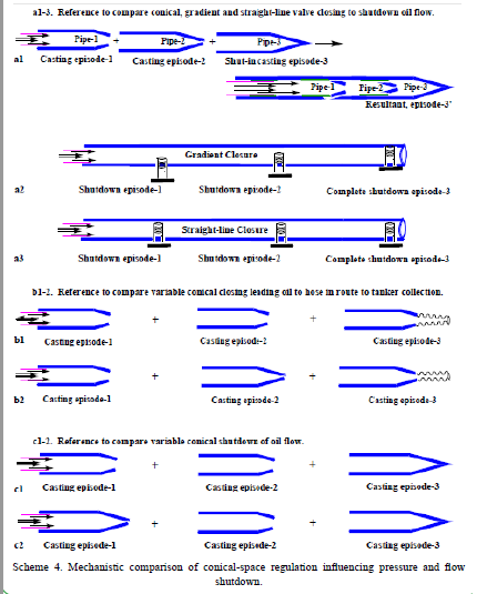
Scheme 4. Mechanistic comparison of conical-space regulation influencing pressure and flow shutdown.
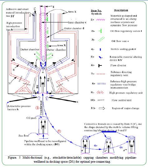
Figure. 5 Multi-fuctional (e.g., attachable/detachable) capping chambers modifying pipelinewellhead in docking space (DS) for optimal pre-connecting.
Conclusion
In this theoretical and conceptual research endeavor, a variety of complementary units to construct a universal component were strategically and graphically designed in the year of 2010. All such units designed were to serve as templates for specialized experts to expand towards the construction of a full-proof apparatuses to bring the flow of oil in the Gulf of Mexico to a complete halt. Many of the aforementioned conceptually designed units were created to be molded into fully operational apparatuses and in numerous instances, were found as coincidental candidates used in the development of a plethora of other new technological apparatuses [19-21]. When comparing all of the inventor’s concepts, machineries and methodologies to those that were actually used to halt the flow of oil in the Gulf of Mexico during the stoppage period in the year 2010, the comparison resulted in a high degree of overlap (i.e., ~ 100%). Many personal literature searches and analyses as to what machineries and methodologies that were actually used, or derivatized to halt the Gulf of Mexico oil spill in 2010 were apparently ongoing from year 2010 until year 2019. It was during the year 2016 that the conclusion of substantial derivatization associated with the theoretical and conceptual constructions of complementary units herein to construct a universal component was most realized. This work shows significant originality, in that a variety of neverbefore built apparatuses to stop the flow of oil in the Gulf of Mexico were rationally and conceptually designed as fully operational apparatuses without having any original replicas as templates. As a reminder for confirmation and motivation, the Author of this publication often asks and answers the question, “what is It that always respond to all ecological detriments with initial, negative and positive counter responses within the environment, but always gives rise to a new optimal ecological balance and harmony”? The Author also believes that someday, this new optimal balance and harmony within the ecological system on our planet will one day be insufficient in maintaining the existence of the human race; especially if we continue to ignore Nature’s ultimate message.
The motivation pertaining to the development of the various multifunctional apparatuses submitted in stopping the Gulf of Mexico Oil Spill during the year 2010 is to be addressed below.
A. A moral obligation to assist positively towards all of God’s creations.---This is a therapeutic benefit to the Author.
B. An economic disaster of the US was imminent.
C. An ecological disaster within the US was imminent. The oil spill was sure to continue throughout the water-ways of the Atlantic Ocean, outlets and tributaries.---This included disastrous possibilities for the southeastern and northeastern regions of the United States.
D. The ability of human presence (i.e., emergency responders) within the surrounding oil spill areas of the ocean was approaching theoretical impossibility. Thus, the gases and oils released were gradually diminishing the density (i.e. buoyancy) of the upper ocean layer with the consequence of not being able to support the weight of physical objects including ships and boats.--- This condition would cause many physical object to sink below the upper oil-gas layer of the ocean as equated with the phenomenon associated with the Bermuda Triangle.
E. The conditions were approaching a real possibility for an unexplainable/unexpected ignition of the flammable gases (e.g., methane) that could fuel the burning of the surrounding oils that would give rise to an explosion of unimaginable magnitude.---This could theoretically cause tsunami episodes and lead to significant human and wildlife casualties.
F. Last, but foremost, the motivation associated with pursuing the stoppage of the Gulf of Mexico oil spill was to preserve the Family of the earth.
Conclusionary Quotes of Ecological Resolutions [22]
A. “The environment is where we all meet; where we all have a mutual interest; it is the one thing all of us share.”----Lady Bird Johnson.
B. “The Earth will not continue to offer its harvest, except with faithful stewardship. We cannot say we love the land and then take steps to destroy it for use by future generations.” ----John Paul II.
C. “Environmentally friendly cars will soon cease to be an option … they will become a necessity.”----Fujio Cho, Honorary Chairman of Toyota Motors.
D. “The proper use of science is not to conquer nature but to live in it.” ----Barry Commoner [Tweet This].
E. “We have forgotten how to be good guests, how to walk lightly on the earth as its other creatures do.” ----Barbara Ward [Tweet This].
F. “Progress is impossible without change, and those who cannot change their minds cannot change anything.” ----George Bernard Shaw [Tweet This].
G. “I only feel angry when I see waste. When I see people throwing away things we could use.”----Mother Teresa.
H. “To me a lush carpet of pine needles or spongy grass is more welcome than the most luxurious Persian rug.” ----Helen Keller [Tweet This].
Acknowledgement
Special thanks to the Family of the Earth as Our oneness continues to inspires Our interdependent obligations in respecting and preserving all of Nature.
Conflict of interest:
author declares that there are no conflicts of interest.
References
BP Deepwater Horizon Gulf Oil Spill (2010) Overview, Green Peace.View
Bos CD (2016) Deepwater Horizon: Disaster in The Gulf - Summary of the Deepwater Horizon Disaster. Awesome Stories.View
BP oil spill timeline (2010) The Guardian.View
Pallardy, R. (2019). Deepwater Horizon oil spill. Britannica.View
Dell'amore, C. (2010). Gulf Oil Leaks Could Gush for Years. National Geographic.View
Johnson, SK. (2012). How an all-star team put an end to the Deepwater Horizon oil spill. ars Technica.View
Mullins, J. (2010). The eight failures that caused the Gulf oil spill. New Scientist.View
Krauss, C., Fountain, H.,& Broder, JM. (2010). Acrimony Behind the Scenes of Gulf Oil. New York Times.View
Laumer, JR.(2010). Worst-Case Scenario for Gulf of Mexico: Double Exploding Methane Triggered Tsunamis, & ... Tree Hugger.
Jamail, D. (2012). BP settles while Macondo 'seeps'. Aljazeera.View
Kistner, R (2011), The Macondo Monkey on BP’s Back. Huff Post.View
David, Biello. (2011)., How Science Stopped BP's Gulf of Mexico Oil Spill. Scientific American.View
Koch, (2015)., Is Deepwater Drilling Safer, 5 Years After Worst Oil Spill? National Geographic.View
Message from BP (2015) Five years of investigation: The Gulf of Mexico is Rebounding.
Deepwater Horizon Oil Spill (2016), Final Programmatic Damage Assessment and Restoration Plan and Final Programmatic Environmental Impact Statement. NOAA.View
About Jerome Milgram (2003) MIT.View
Mallinson, A. (2014)., The Sherlock Homes of the Sea.View
Kamila, S. (2013). Introduction, Classification and Applications of Smart Materials: An Overview. Am J Applied Sci 10: 876- 880.View
Chen, J., Xunke, L., Wenhui, X.,& Yongtian, K. (2013). Capping stack An industry in the making: An Overview. Semantic Scholar.
Madrid, M.,& Matson, A. (2014). How Offshore Capping Stacks Work. Society of Petroleum Engineers (SPE) Inc [US].View
Mazerov, K. (2011). No longer niche: Expandables finally going mainstream. Drilling Contractor.
Brassaw, B. (2019)., 23 of the Greatest Environmental Quotes. Earth 911.View