
- About the Journal
- Editorial Board
- Review Process
- Author Guidelines
- Article Processing Charges
- Special Issues
- Current Issue
- Past Issue
 Current Research in Materials Chemistry
Current Research in Materials Chemistry Volume 3 (2021), Article ID: CRMC-108
https://doi.org/10.33790/crmc1100108Review Article
Carbon Capture Materials and Technologies: A Review
Zachary Luedtke1,Zhao Sun3, Matthew Aro2, Sam Toan1*
1Department of Chemical Engineering, University of Minnesota-Duluth, Duluth, MN 55812, USA.
2Natural Resources Research Institute, University of Minnesota-Duluth, Duluth, MN 55812, USA.
3School of Energy Science and Engineering, Central South University, Changsha 410083, China.
Corresponding Author Details: Sam Toan, Department of Chemical Engineering, University of Minnesota-Duluth, Duluth, MN 55812, USA. E-mail: stoan@d.umn.edu
Received date: 16th December, 2020
Accepted date: 30th January, 2021
Published date: 01th February, 2021
Citation: Luedtke, Z., Aro, M., Sun, Z., & Toan, S. (2020). Carbon Capture Materials and Technologies: A Review. Cur Res Mater Chem 3(1): 108.
Copyright:©2021, This is an open-access article distributed under the terms of the Creative Commons Attribution License 4.0, which permits unrestricted use, distribution, and reproduction in any medium, provided the original author and source are credited.Creative Commons Attribution License, which permits unrestricted use, distribution, and reproduction in any medium, provided the original author and source are credited
Abstract
The United States emitted 5.27 billion tonnes of carbon dioxide into the atmosphere in 2018, less than one-sixth of the global emissions that year. The immense amount of greenhouse gases in the air have a detrimental effect on the planet. Rising global temperatures, rising sea levels, drought, wildfires, and other natural disasters are all being accelerated because of carbon emissions. Carbon capture is one solution that could reduce emissions tremendously. The topics of energy consumption, transportation phenomena, and thermodynamics of a wide range of carbon capture methods will be discussed.
Keywords: Climate Change, Post-combustion, Carbon Dioxide, Carbon Capture, Absorption, Desorption
Introduction
In 2018, the United States emitted 5.27 billion tonnes of carbon dioxide (CO2) into the atmosphere [1], while global energy-related emissions rose to a historic high of 33.1 billion tonnes of CO2 [2]. And with global emissions projected to increase by a third from 2012 to 2040 [3], drastic changes are needed in order to mitigate the effects of climate change.
CO2 is the most abundant greenhouse gas (GHG) at 83.83% of total GHGs [4]. Although CO2 absorbs less heat per molecule than other GHGs, like methane and nitrous oxide, it is more concentrated and lasts longer in the atmosphere [5]. It is emitted from the burning of fossil fuels such as coal and petroleum-based products as well as other sources, including biomass. After combustion, CO2 is released into the atmosphere, which causes a warming effect on the planet. This will cause a rise in global temperature, a rise in sea levels and a greater intensity of droughts, wildfires, and other natural disasters. Even though GHGs have been directly linked to climate change, fossil fuels still control the energy market in the United States and around the world. In 2015, 81.5% of the United States’ total energy demand was provided by fossil fuels [6]. Once the CO2 is in the air, there are few ways in which it can be removed. Only about half of annual emissions are absorbed by the ocean and vegetation. Even if humans were to stop burning fossil fuels altogether, removing the remaining CO2 with natural sinks would take a long time. Researchers have estimated that about 50% of the manmade CO2 would be absorbed in 50 years, and the remaining 50% would be in the atmosphere for upwards of tens of thousands of years [7].
Because it is highly unlikely that the use of fossil fuels will be extinguished in the next few years, practical solutions for CO2 removal must be implemented. Carbon capture technologies could drastically reduce carbon emissions by stopping CO2 from entering the atmosphere. Carbon capture involves the separation of CO2 from industrial processes and energy-related point sources, such as power plants and other industrial plants that consume large amounts of energy. The concept of carbon capture is not new as the separation. The separation of CO2 has been a common practice in the oil and gas industry since the 1920s [8]. The process, first developed to enhance the quality of the products coming from crude oil, is still being used. The product is “sweetened” by the reduction in acidity with the extraction of CO2. The first Carbon Capture and Sequestration (CCS) program was not started until 1989 at the Massachusetts Institute of Technology. This program was started as a means to find different ways of removing CO2 from emission sources such as gas processing and ethanol production [9]. Since then, there have been many advances in carbon capture technology and development of several different methods.
The three main categories of carbon capture are pre-combustion, post-combustion and oxyfuel combustion. Pre-combustion carbon capture is mainly used during the production of a gaseous mixture called syngas, which consists primarily of carbon monoxide and hydrogen. The carbon monoxide is converted to CO2 and separated from the mixture, yielding a raw syngas that can be used for chemical production or energy feedstock of heat. Oxy fuel combustion uses nearly pure oxygen, rather than air, to combust fuel that will produce a flue gas that is mostly composed of CO2 and water vapor. This stream is dehydrated to obtain high-purity CO2. Lastly, postcombustion capture focuses on capturing the CO2 after fossil fuels have been combusted, usually in an industrial or power plant [10]. Post-combustion carbon capture will be the focus of the remainder of this paper.
Carbon capture is a vital technology for mitigating the effects of climate change. One German study illustrates the potential that carbon capture can have on global emissions. It states that chemical production is set to become the largest consumer of global oil by 2030. By capturing CO2 from industrial processes, or directly from the air, and utilizing it as an alternative carbon source for chemicals, this technology has the potential to reduce annual GHG emissions by up to 3.5 gigatonnes of CO2 equivalents in 2030 [11]. Such a dramatic decrease in emissions would have numerous benefits, including slowing the rate of climate change. Of the models cited in the Intergovernmental Panel on Climate Change's Fifth Assessment Report, more than half require carbon capture to obtain the goal of staying within 2°C of warming from the pre-industrial period [12]. The remaining models without carbon capture rose in price by 138% to reduce the same amount of emissions. Although carbon capture can provide an economical method of effectively reducing emissions, there are only 18 global carbon capture projects in operation today [13].
Liquid solvents are the most popular method of carbon capture in operation today. All of the major carbon capture facilities in 2015 were using either physical or chemical solvents for their method of capture [14]. Physical and chemical solvents have similar physical properties but differ in that physical solvents are based on gas solubility instead of a chemical reaction. Physical solvents typically have a larger absorption capacity than chemical solvents, which enable lower solvent recirculation rates. However, physical solvents often have difficulty meeting gas specifications because they are less selective than chemical solvents. For these reasons, physical solvents are usually seen in pre-combustion carbon capture facilities. Chemical solvents such as methyldiethanolamine (MDEA) are primarily used in post-combustion facilities because of their large CO2 absorption capacity.
Monoethanolamine (MEA) is another chemical solvent that is widely used in post-combustion carbon capture. MEA is a clear, colorless, viscous liquid often used for detergents, personal care products and wood treatment [15]. Amine solvents are the most used chemical for carbon capture. Other amines such as diethanolamine (DEA) and MDEA have been used in industry for many years for gas purification [16]. However, MEA has advantages over other amines because of its unique features, such as high loading capacity for CO2 at low partial pressures, fast reaction kinetics and high removal efficiencies [17]. The cost of the solvent is also relatively low, but it is known to be corrosive and its regeneration requires a significant amount of energy [18]. MEA is one of the most researched and which suggests commercial availability to me. The aforementioned disadvantages of MEA could be why carbon capture has not been more widely implemented.
The use of ionic liquids for carbon capture has been gaining traction. This is a relatively new process, with the first industrial use occurring in 2003. The term “ionic liquid” refers to any liquid that is composed entirely of ions at a temperature around or below 100°C [19]. A primary reason why ionic liquids are being researched to replace conventional solvents is their low volatility. Because ionic liquids have virtually nonexistent vapor pressure, the replacement of conventional solvents with ionic liquids would prevent the emission of volatile organic compounds (VOCs), which are a major source of environmental pollution. Another advantage of ionic liquids is the number of possible solvents. There are at least one million different binary ionic liquids and as many as 1,018 ternary ionic liquids that are potentially possible. This is compared to the 600 molecular solvents that are in use today. The number of possibilities allows the solvent to be designed to achieve optimal absorption and selectivity. Other appealing properties of ionic liquids are their high thermal stability, large electrochemical window and ability to dissolve compounds with various polarities [20]. One drawback of ionic liquids for carbon capture, however, is their high viscosity due to the complex synthesis and purification processes. Higher viscosities are not suitable for carbon capture because this slows the absorption rate and increases the costs for pumping due to the increase in resistance of flow. This can be improved by using the proper combination of cations and anions. Because the cation usually has little effect on the viscosity, decreasing the alkyl chain of cations can also decrease the viscosity. Ionic liquid research is still in the very early stages.
Solid sorbents are another method of post-combustion carbon capture with promising features, including potential energy savings, Is this greater adsorption capacity?, selectivity, and ease of handling [21]. An adsorbent system with a working capacity of at least 3 mmol/g could see a reduction in the energy requirement by 30-50% compared to that of an amine-based system [22]. Samanta et al. proposed the following criteria to consider when selecting a sorbent material.
• Adsorption capacity: this indicates the amount of sorbent needed. A high adsorption capacity reduces both the sorbent quantity and size of process equipment. To compete with an MEA scrubbing system, the CO2 working capacity (defined for a short adsorption time) must be between 3 and 4 mmol/g of sorbent.
• Selectivity for CO2: defined as the ratio of the CO2 capacity to that of another component at a given flue gas composition. The selectivity has a direct effect on the purity of the captured CO2. Because flue gas is largely composed of N2 and water vapor, it is important to use a material with a high selectivity for CO2.
• Adsorption/desorption kinetics: this also has a large impact on how much adsorbent is needed for the process. The faster the sorbent can adsorb and desorb CO2, the less of it will be needed.
• Mechanical strength of sorbent particles: this includes the microstructure and morphological stability of the sorbent. Good retention of stability during multiple cycles of regeneration is key for high kinetics. The mechanical strength of the sorbent is also very important for minimizing the makeup rate, which will render the process more cost-effective.
• Chemical stability/tolerance to impurities: solid sorbents should exhibit stability in an oxidizing flue gas and resistance to common contaminants, such as SOx, NOx, and heavy metals, which will most likely need to be removed because of their negative effect on the CO2 adsorption capacity.
• Regeneration of sorbents: the heat of adsorption should be substantially should be low, ranging from -25 to -50 kJ/mol for physisorption and -60 to -90 kJ/mol for chemisorption. Low heat of adsorption will reduce energy requirements and costs for regeneration.
• Sorbent costs: According to a sensitivity analysis done by Tarka et al. [23]], a sorbent's cost should be from $5 to $15 per kg. $5/ kg is the best-case scenario, while the most realistic scenario would be near $10/kg.
Once an adsorbent is chosen based on the aforementioned criteria, a method of cyclic adsorption is considered. The adsorption-desorption process is accomplished by three main methods: temperature swing adsorption (TSA), pressure swing adsorption (PSA) and vacuum swing adsorption (VSA) [24]. Both PSA and VSA utilize a reduction in pressure of the adsorbent fixed column. The difference lies in how the pressure is decreased. In PSA, the column is filled with gas until saturation, after which the pressure in the column is decreased to atmospheric pressure, which results in desorption. In VSA, desorption occurs due to an applied vacuum in the column. TSA is a method of desorption that involves heating the adsorbent until the desorption temperature is reached. The temperature swing more easily forces the CO2 off the surface of the adsorbent, while changing the pressure more easily moves the gas out of the column after desorption.
Activated carbon is another solid being researched as a potential method of carbon capture. Activated carbon is a purified, powdered charcoal that is treated either physically or chemically to create microfissures that drastically increase the surface area of adsorption. The surface area of activated carbon can be as large as 500 to 1500 m2/g [25]. The use of porous carbon in the form of charcoal can be traced as far back as early 1550 BC in ancient Egyptian papyrus. However, it was not commercially produced until the beginning of the 20th century during World War I to be used in protective gas masks [26]. Today, activated carbon is commonly used for purification of water and products in the chemical, pharmaceutical and food industries. Common commercial activated carbons include FPV, WG-12, and CWZ-22, which are intended for water treatment, but have been used for testing of carbon capture [27].
Coconut shell is often used as a raw material for activated carbon because of its low cost, high Brunauer-Emmett-Teller (BET) specific surface area (the amount of adsorbate gas per unit of surface area) and high porosity [28]. The coconut shells are usually gathered from the country of origin to later be prepared by drying the shell, cutting into small pieces, and putting into a high-temperature kiln for carbonization. Testing by Huang et al. showed how activation temperature and activation times affected the resulting activated carbon. Increasing the activation temperature and time increases the ash content, pH, BET specific surface area and total pore volume (which would increase the CO2 adsorption capacity), but significantly reduces the charcoal yield. Their results also showed that coconut shell activated carbon has a higher instantaneous adsorption capacity than commercial activated carbon.
Metal Organic Frameworks (MOFs) are a relatively new class of crystalline porous materials constructed from multi-metallic units called secondary building units (SBUs) and organic linkers [29]. MOFs' physical and chemical properties can be finely tuned for the desired product by designing and functionalizing SBUs, linkers and pore environments, rendering them useful for a variety of applications, such as gas storage and separation, heterogeneous catalysis, sensing, drug delivery and more. In terms of carbon capture, MOFs have numerous unique features: e.g., predictable, functionalizable structures (predicting the structures of many MOFs to allow for incorporation of different types of accessible capture and catalytically active sites); hybrid structures (e.g., MOFs are compatible with other materials and can be used as a template for other MOF derivatives with specific chemical and physical properties); and particular strengths for catalysis (e.g., MOFs have the ability to combine beneficial features of homogeneous and heterogeneous catalysts such as high catalytic efficiency, reusability, and stability).
MOFs consist of metal-based nodes (single ions or clusters) and are connected by organic linking groups to form a one-, two- , or three- dimensional coordination network. The basis for the synthesis of MOFs is achieved by employing a modular synthesis (metal ions and organic ligands are combined to form a crystalline, por-ous network) [30]. There are several synthesis methods, each resulting in various desired properties. The synthetic procedures usually include a wide range of temperatures, solvent compositions, reagent ratios and concentrations, and reaction times. The finetuning of these parameters is critical for optimizing the synthesis of the specific material. One of the most studied MOFs is Zn4O(BDC)3 (MOF-5) which consists of tetrahedral [Zn4O]6+ clusters bridged by ditopic BDC2-ligands that form a cubic, three-dimensional network. Functionalized derivatives of MOF-5 can be prepared using other linear dicarboxylate linkers.
One of the greatest advantages of using MOFs for carbon capture is also one of its disadvantages. There is a massive variety of MOFs with different properties that can be produced by changing the combination of metal clusters and organic ligands; searching through the different MOFs for certain applications is time consuming. However, molecular simulations have been utilized to determine which materials in a MOF are best suited for carbon capture [31]. Daglar et al. screened through the most complete and recent MOF database, the Cambridge Structural Database, to find the best materials for membrane-based CO2/N2 separation. Two simulations (grand canonical Monte Carlo (GCMC) and Molecular Dynamics (MD)) were performed to acquire data for adsorption and diffusion of CO2 and N2 in all MOFs under infinite dilution conditions. Using these results, the selectivity and gas permeability of 3,806 different MOFs were estimated and compared with widely studied polymers and zeolites. Further GCMC and MD simulations of 15/85 CO,2/N2 mixtures were then carried out on the top 15 MOFs to find the separation performances of flue gas. These MOFs were found to have a selectivity ranging from 15-820 and CO2 permeability of 1.19E5 – 1.95E6 Barrers. A final simulation was performed to investigate the effect of water on the selectivity and permeability of these MOFs. The gas mixture, which was 10/87/3 CO2/N2/H2O, showed that the presence of water produced inferior results compared to the dry simulation. Lastly, it was determined that the best MOFs for CO2/N2 membrane-based gas separation were made from materials with more narrow pores, lower surface area, and which contained monoclinic and lanthanide.
Porous amino-solids were first coined in 2015 by Didas et al. [32] and can be divided into three subclasses based on their bond structure and preparation methods. Materials found in class 1 rely on physical amine impregnation into available pore windows of a mesoporous solid support (usually silica), which is usually silica. This is done by stirring the support for 12 to 24 hours with the amine in methanol. The solvent is then extracted at approximately 70°C to impregnate high levels of amine into the pore windows and is retained in that space via van der Waals’ forces. Larger aminopolymers are typically used for the class 1 materials. Aminopolymers such as polyethyleneimine (PEI) have larger chains, which produce greater van der Waals’ forces and therefore have better cyclic retention. Shorter amines like MEA and MDEA are usually used for class 2 and class 3 adsorbents because of their lower activation energy; this aids the facilitation of tethering. Class 2 amino-solids utilize covalent organosilane grafting onto the target interfaces. These materials are prepared by dissolving the amino-silane in a volatile solvent such as toluene. The adsorbent is then added to the solution and heated under reflux at approximately 80°C for 24 hours. After the grafting occurs, the primary solvent is replaced with a secondary volatile solvent, usually hexane, to fully activate the adsorbent. Class 2 materials have multiple covalent bonds per amine center. Class 3 materials are prepared in the same fashion as class 2, but only contain one covalent bond for each amine molecule.
A membrane is defined as a physical barrier that either completely stops or reduces the flow of a given compound and can be used as a method of separation [33]. It is a porous media that only allows for the flow of compounds smaller than the pore diameter. Some factors allow molecules with a larger diameter than the membrane's pore size to flow, but this only occurs in specific situations. Membranes can be seen in nature in several different processes. Without membrane filtration, trees would not be able to stand straight, and human life would look drastically different because there would be no way to create a cellular environment that is different from the surrounding environment. Separation with membranes is possible because of the gradient across the membrane. Membranes can be classified based on the type of gradient. The two main groups are pressure-driven and non-pressure-driven flows. The pressure gradient is called the transmembrane pressure (TMP) and is the driving force of the pressure-driven membrane processes. Examples of such pressuredriven processes are microfiltration, ultrafiltration, nanofiltration and reverse osmosis. The most common gradient in non-pressure-driven flows is a concentration gradient. Examples of such non-pressuredriven flows are dialysis (concentration-driven), electrodialysis (electrically-driven) and forward osmosis. This technology can be applied to carbon capture as well. Polymeric membranes are one of the most common with several advantages such as adaptability, operational simplicity, low energy consumption, capital cost and fewer environmental impacts [34].
Cryogenic separation is different than the previously discussed methods because it is a mostly physical process that depends on the condensation and freezing point of the components in the flue gas. In other words, this process will drastically increase the pressure and decrease the temperature in order to achieve a phase change of the CO2 gas to a liquid or solid to then be separated. Cryogenic separation does not use chemical absorbents, and it delivers a highpurity, dry CO2 product stream [35]. There are two sub-categories of cryogenic separation. This method: desublimation and cryogenic. Desublimation processes separate the CO2 as a solid frost at conditions below the sublimation temperature (195 K at 1 bara). The frost is later warmed above sublimation conditions to produce a pure CO2 stream. Cryogenic processes achieve similar results by separating CO2 in liquid form. Desublimation systems are almost solely based on temperature change and operate at atmospheric pressure, while cryogenic separation involves energy-intensive raw gas compression stages. Desublimation processes can also achieve capture ratios of nearly 100% while removing both water and CO2, eliminating the need for drying stages. For this process to be competitive, it is vital to effectively integrate a refrigeration system or low-cost chilling source that can meet cooling demands.
There have been several studies on combining cryogenic separation with other methods, such as membrane separation. Combining the two methods could eliminate some of the limitations of each. For example, with a fixed permeability, the CO2/N2 selectivity reaches an upper limit, the same being true for the reverse [36]. The use of a membrane will reduce the amount of N2 that needs to be cooled during the cryogenic process, which will substantially decrease costs. Furthermore, specific membranes, when operated below -20°C, have up to a 400% increase in CO2/N2 selectivity compared to operation at room temperature [37]. The process proposed by Hasse et al. starts by compressing the flue gas to 220 psi, followed by drying and cooling to -30°C. It then passes through the membrane which separates the CO2 from the rest of the stream. The flow through the membrane is counter-current with a small fraction of the CO2-depleted stream offsetting the negative effect a higher recovery has on membrane productivity. This has been shown experimentally and via simulations to reduce the minimum area of the membrane, which will reduce cost. The CO2 is re-compressed and fed into a cryo-phase separator to create liquid CO2 at 60 bar and 20°C. Similar processes have also been proposed and optimized. A study by Mat et al. determined the most cost-effective way to run a hybrid membrane-cryogenic postcombustion carbon capture process. Several variables were analyzed, such as condensation pressure and temperature, O2 concentration in the boiler, and membrane design. The product constraints consisted of a 90% CO2 recovery and a minimum purity of 95%. It was found that the O2 concentration in the boiler should be approximately 18% and that a lower pressure does not necessarily mean lower cost. Although there would be less compression, to achieve the same selectivity, the area of the membrane must increase, which increases capital costs. The levelized cost of energy (LCOE) was not greatly affected by the pressure ratio at fixed condensation conditions nor varying condensation conditions at a fixed selectivity. The optimum CO2/N2 selectivity to minimize the LCOE ranged from 55-70.
Although capture efficiency in terms of absorption and desorption rates are very important for a carbon capture facility, costs are more than likely the limiting factor. No matter how efficient a sorbent is, if it is not economical, there is only a minimal chance of a successful, long-term commercial operation. Duke Energy Inc., North America’s largest power generator, partnered with Huaneng Power Group, the world’s largest power company, to determine the most economical amine-based carbon capture method [38]. In this study, they evaluated the costs of using 30 wt% MEA, 35 wt% amine blend and a 20 wt% MEA plus TiO(OH)2 catalyst [39] at two different natural gas combined cycle (NGCC) plants. Both carbon capture processes for each plant were simulated in Aspen Plus. Each plant had a CO2 capture capacity of 1 million short tons with a 90% capture efficiency. A full technoeconomic evaluation compared these three methods of capture at the two different plants. The factors that lead to the total variable costs were losses to energy generation, costs for consumed materials and utility costs. At both locations, the variable cost associated with the use of 20 wt% MEA with catalyst was substantially lower, with a 43.5% reduction compared to the base case (30 wt% MEA), while the 35 wt% mixed amine method averaged only 26.5%.
Energy Consumption
Reaction Kinetics
As mentioned, a major limitation of the benchmark absorbent, 30 wt% MEA, is the amount of energy required for regeneration. This is mainly due to the high specific heat and enthalpy of vaporization of the water solvent. The energy required for solvent regeneration alone accounts for approximately 70% of the total cost of carbon capture [40]. Li tested the performance of newly developed absorbents for energy-efficient carbon capture using a variety of absorbents, including aqueous potassium lysinate, blends of MEA with 2-methoxyethanol (EGME) and 2- ethoxyethanol (EGEE), 2-(methylamino)ethanol (MAE) with diethylene glycol dimethyl ether (DEGDME), potassium prolinate/EGME/water, and potassium sarcosinate/EGME/water. The purpose of the testing was to see if replacing the water in common absorbents with organics would improve the desired characteristics and address the disadvantages of the high-performing conventional aqueous amines. In comparison to water, these solvents have higher boiling points, lower specific heat capacities and low vaporization enthalpies. These properties can reduce energy demands for regeneration by lowering sensible and latent heat. Amino acid salts could be a good alternative because of their high kinetics, low volatility and good resistance to degradation. In terms of CO2 loading, the results showed numerous improvements. The base comparison was 5.0 M MEA solution, which had a cyclic capacity of 0.841 mol CO2/kg solution. (The cyclic absorption capacity is estimated from the difference of CO2 loadings under the absorption and desorption conditions, 313 K and 353 K with N2 strip method, respectively.) By replacing water in the MEA solution with non-aqueous glycol ether solvents, the cyclic capacities increased 45-65%. The aqueous 5.0 M MEA was estimated to have an overall heat duty of 415 kJ/mol CO2. By using the single-phase, non-aqueous absorbents, the CO2 desorption efficiency was similar to the baseline with a nearly 50% reduction in overall energy consumption. This research is promising for increasing CO2 loading and decreasing energy consumption.
Another method for improving the performance of MEA is through the addition of a catalyst to speed regeneration of the solvent and allow for desorption to occur at much lower temperatures. This could dramatically reduce energy consumption and amine losses, while preventing emissions of amine-based byproducts from decomposition [41]. Lai et al. tested the effects of using TiO(OH)2 as a catalyst for both the absorption and desorption with MEA. The flue gas consisted of 10 vol% CO2, 10 vol% O2, and 80 vol% N2. When compared to 20 wt% MEA with and without TiO(OH)2, the effective sorption period drastically increased when the catalyst was present. 90% of CO2 in the flue gas was able to be captured, corresponding to a 75% improvement over MEA without catalyst (162 mmol CO2 absorbed) and MEA with a catalyst (283 mmol CO2 absorbed). The rate of desorption is also much higher at low temperatures. The highest desorption rate of spent MEA with the presence of TiO(OH)2 was 0.204 mmol/s; this was achieved after only 792 s. The spent MEA without catalyst was only able to reach 0.0162 mmol/s after the same period of time. Because the rate of desorption is increased with the catalyst, the total amount of CO2 desorbed also increased by approximately 86%, from 34.5 mmol CO2 with just MEA to 64.1 mmol CO2 when the catalyst is added. A similar improvement was seen with other amines, such as MDEA. Only 2.12 mmol CO2 is desorbed from the spent 20 wt% MDEA solution, while 8.72 mmol CO2 can be desorbed with the presence of TiO(OH)2. The stability of TiO(OH)2 was also investigated to determine how well the catalyst retains its catalytic properties after several cycles. After 50 sorption-desorption cycles, there was no obvious decrease in CO2 sorption or desorption. With these improvements, the simple addition of TiO(OH)2 to MEA can significantly accelerate both absorption and desorption, lower the temperature needed for desorption and, in turn, drastically lower the energy requirements and operating costs for carbon capture.
Similar to organic sorbents, inorganic sorbents are very inefficient in terms of desorption. The desorption process is very energyintensive, which drastically increases costs. But, organic-based capture methods are less cost-effective due to high decomposition rates and toxicity. Inorganic aqueous sorbents are much more costeffective and have been proven to be suitable for carbon capture through the Benfield Process [42]. Toan, et al. tested the effects of TiO(OH)2 on the CO2 desorption rate at lower temperatures. They used a 10 wt% water solution of KHCO3 as the inorganic sorbent and 3 wt% nanostructured TiO(OH)2. The rate of desorption improved by as much as 360% when the catalyst was added. They also tested how the concentration of the catalyst affected the desorption rate. The percent ratio of the desorption rate with the catalyst compared to that without peaked at over 1200% with a catalyst concentration of 4 wt%. These tests were completed at 60°C, which was found to be a sufficient temperature when using TiO(OH)2, compared to 100°C when the catalyst was not used. These findings provide multiple benefits: a faster desorption rate, resulting in smaller reactors and lower capital costs; lower desorption temperatures leading to lower energy requirements that could be satisfied by the existing wasteheat energy streams; and use of inorganic sorbents, which reduces (and possibly eliminates) the toxic emissions and sorbent losses commonly found with amine sorbents.
The process of using potassium-based sorbents, more specifically potassium carbonate (K2CO3), for the removal of CO2 from high pressure gases such as synthesis gas has a long history. Challenges with using K2CO3 for carbon capture include slow rate of reaction and high solvent circulation rates, leading to large solvent regeneration energy requirements [43]. However, there are several benefits to using potassium-based sorbents as opposed to MEA. There is a patent from 2013 by CO2CRC of a precipitating potassium carbonate process (also known as UNO MK 3) [44], which uses a highly concentrated solvent that could improve the kinetics and reduce energy consumption. A pilot plant was built at the University of Melbourne to test the hydraulic aspects of carbon capture with a precipitating solvent and to validate a simulation model developed in Aspen Plus. The concentration of the solvent ranged from 20 to 30 wt% and the pilot plant was able to capture 4 to 10 kg/hr of CO2 from an air-CO2 mixture of 30 to 55 kg/hr.
Ionic liquids are sorbents that have advantages over MEA as well. Although the CO2 absorption capacity in previously studied ionic liquids is only about 0.03 mol CO2/mol ionic liquid [45], the low absorption is largely due to the extremely high viscosity and the complex synthetic routes of most task-specific ionic liquids. A specific type of ionic liquid called protic ionic liquids (PILs) have recently gained attention for carbon capture due to their simple synthetic routes and lower costs compared to other ionic liquids. PILs are easily obtained through the neutralization of a Brønsted acid and base. Because basicity of ionic liquids plays such a large role in the absorption of CO2, Li et al. designed and synthesized three basic PILs by neutralizing tetramethylguanidine (TMG) with different weak proton donors: imidazole (Im), pyrrole (Pyrr) and phenol (PhO) with different pKa values. CO2 absorption performance, effects of anions and temperature on absorption, and recyclability in the absence and presence of water were evaluated. The results showed that the basicity of the PIL directly affected the CO2 absorption. The ionic liquids with a higher pKa value had a higher absorption. The highest absorption capacity was found to be 0.83 mol CO2/mol PIL and was obtained at 40°C and 1 bar in a 93 wt% [TMGH][Im]-7 wt% H2O system. Good recyclability was also found in this PIL. Four absorption-desorption cycles were conducted, indicating that [TMGH][Im] could be a viable alternative for carbon capture.
Deep eutectic solvents (DESs) are an advanced sub-category of ionic liquids that possess many of the advantages of ionic liquids; however, compared to conventional ionic liquids, the cost to synthesize them is lower and the method is less complex [46]. Previous studies have obtained DESs by mixing a hydrogen-bond acceptor (HBA), such as choline chloride, with a hydrogen-bond donor (HBD), such as urea. Although ChCl-glycerol (1:2) achieved a solubility capacity of 1.20 mol CO2/mol DES, it was only possible at 58.6 bar. When this same DES was tested again at 1.87 bar, the solubility dropped to only 0.047 mol CO2/mol DES. Conventional DESs cannot obtain adequate absorption at ambient pressures, primarily because the capture of CO2 is done via physical interactions (hydrogen bonds, van der Waals forces, etc.). Efforts to mitigate this problem have been made, including changing the absorption mode of DESs from physical to chemical. Much of this research used HBA or HBD with an amino group and found great improvements in absorption capacity. In the case of [MEA. Cl][EDA] (1:3), the absorption was increased to 1.456 mol CO2/mol DES; however, the stability of this DES was reduced. The decomposition temperature of one such DES, BmimCl−MEA (1:1), was only 86°C. With such a low decomposition temperature, there will be absorbent loss in the regeneration process, which results in higher operating costs. Na et al. studied ways to mitigate these problems by using a task-specific DES containing an aprotic heterocyclic anion with high thermal stability. A series of imidazolederived DESs were obtained by mixing BmimCl and imidazole at varying molar ratios. 1,5-diazabicyclo [4.3.0] non-5-ene (DBN) was then added to the DES to make the task-specific DES. DBN− BmimCl−Im showed the greatest absorption, with a value of 1.02 mol CO2/mol ionic liquid. By changing the mole ratio of BmimCl and imidazole, the absorption rate also changed. DBN− BmimCl− Im (1:1:2) reached absorption equilibrium in only 30 minutes, while only slightly decreasing the absorption capacity. The absorption enthalpies were able to be manipulated by changing the ratio. DBN− BmimCl−Im (1:1:2) had the lowest absorption enthalpy, -40 kJ/mol, which allowed for better recirculation. This DES also had the highest decomposition temperature of 146.5°C. In addition, the reusability of the DES proved to be sufficient after six absorption-desorption cycles.
Activated carbon is commonly derived from coal, but it can also be derived from walnut and coconut shells due to their high density, high cellulose content, ease of access and low cost. Asadi-Sangachini et al., who studied the use of activated carbon from walnut shells, tried to reduce costs using chemical activation instead of physical activation. Chemical activation has advantages such as lower applied temperature, shorter running time, higher carbon yield and no formation of tar or volatile matter [47]. These characteristics were tested by using KOH (KH) and H3PO4 (HP) to activate the walnut shells. These activating agents were chosen because of their availability, BET surface areas? and high activated carbon yields. Two methods of activation were tested: carbonizing the walnut shells at 600°C (precursor) and using the chemical activating agent (KH, HP). The CO2 adsorptions and porosities of the activated carbon were measured, as well as adsorption optimization, comparison of CO2 adsorption with other organic materials, and costs. By comparing the CO2 adsorption capacity of each test that varied the pressure (1-25 bars), temperature (15-75°C) and activation ratio (0.5-2.5% w/w) of KH and HP, it was found that the optimum precursor is at ambient pressure and 30°C, and the activating agent ratios were 1:2.5 and 1:1.5. The optimum temperatures were 550 and 900°C for activation with HP and KH, respectively. Furthermore, HP2.5 showed the highest capture of 3.55 mmol CO2/g at 1 bar and 30°C. This was a significant improvement over commercial activated carbon, which has a capture of 1.67 mmol/g. HP2.5 did, however, see a reduction in reversibility potential of 2.79 after 10 regeneration cycles. The price of this walnut shell-based activated carbon was calculated to be $1.83/kg, which is highly competitive with most commercially available activated carbon.
There have been studies on various inorganic activated carbons, such as activated nanoporous carbon adsorbent derived from waste plastic or polyethylene terephthalate (PET). PET is an incredibly abundant resource with little economic value and high carbon content [48]. This activated carbon was produced by directly carbonizing the plastic at different temperatures (500-800°C) followed by chemical activation using a range of KOH-to-carbon impregnation ratios. Breakthrough experiments to assess the adsorption-desorption performance were completed under dynamic conditions in a fixedbed adsorption set up. The activated carbon sample with the best textural properties was obtained at 700°C with a 3:1 KOH-to-carbon mass ratio. It showed a BET surface area of 1690 m2/g, a micropore volume of 0.78 cm3/g and the highest CO2 uptake of 1.31 mmol/g at 30°C and a CO2 concentration of 12.5%. This could be an effective method for capturing carbon while simultaneously utilizing waste plastic.
Solid amine sorbents combine the benefits of amine sorbents, such as MEA and MDEA, with various adsorbents. It involves a suitable adsorbent with a porous surface that allows an amine to be attached. Common porous support materials include three mesoporous silica (MCM-41, SBA-15, and KIT-6) and two polymeric supports (PMMA and PS) [49]. But amino-solids can be seen in multiple different adsorbents such as amine-functionalized metal oxides, zeolites, activated carbon and metal-organic frameworks [50]. Silica is also used for amino-solids that of its high resistance to steam and good mechanical and thermal stability.
MCM-41 is a silicon dioxide-based mesostructured compound usually found in a powdered form [51]. When MCM-41 is impregnated with tetraethylenepentamine (TEPA), the amine adsorbent M-MCM-T is created. When analyzing this adsorbent, Zhou et al. took interest in the mechanical strength, textural properties and CO2 adsorption capacity [52]. By crushing samples, the mechanical strength of MCM-41 was found to be 60 N/cm. The addition of montmorillonite, used as a binder in the making of M-MCM-T, on average, increased the strength up to 112.2 N/cm for 40M-MCM. The surface area of the samples was calculated using the BET method and the pore volume and size distribution were calculated using the Barrett-Joyner- Halenda model. The BET surface area ranged from 861 to 648 m2/g, with a negative correlation between the amount of added montmorillonite and BET surface area. The pore volume also decreased as the montmorillonite increased, ranging from 1.07 to 0.59 cm3/g. Lastly, the CO2 adsorption was measured by thermogravimetric analysis (TGA) to find the incremental weight in a 12% CO2/88% N2 stream at 75°C. Both the amount of montmorillonite and TEPA were varied in this experiment. When the impregnation amount was held constant, the adsorption capacity decreased with increasing amounts of montmorillonite. However, as TEPA amounts increased, so did adsorption capacity, with a maximum of 112.8 mg CO2/g adsorbent in 25M-MCM-T55. To analyze energy consumption and costs, the process was modeled after a four-step temperature vacuum swing cycle (TVS). The adsorption occurred at 75°C and ambient pressure while the desorption occurred at 100°C and low pressure. The heat required for desorption came from the lowpressure steam from the flue gas heat recovery. The reason TVS was chosen over other processes is because of its thorough desorption, output of high purity product, and low energy consumption. The total cost of the carbon capture process using 25M-MCM-55T was was estimated to be $28.32/tCO2, including both operating and material costs. The total energy consumption was approximately 3.82 GJ/tCO2, which is much lower than absorption using MEA, which ranges from 4.2 to 4.8 GJ/tCO2.
MUF-16 (Massey University Framework) is a series of materials prepared by combining 5-aminoisophthalic acid (H2aip), an inexpensive and commercially available linker, with cobalt(II), nickel (II), or manganese (II) salts in an alcoholic solvent. This creates a family of compounds referred to as MUF-16 (M=Co), MUF-16(Ni) and MUF-16(Mn). MUF-16 has the potential for carbon capture due to its good thermal stability, resistance to corrosion from water and air, large surface area, and large total pore volume [53]. These MOFs can also absorb a considerable amount of CO2, with MUF-16(Mn) able to adsorb 2.25 mmol/g (50.5 cm3/g) which equates to approximately 0.9 CO2 molecules per metal site. Selectivity tests showed only modest amounts of gases commonly found in flue gas (H2, Ar, N2, CH4, O2, partially combusted fuel). MUF-16 only took up 1.32 cm3/g of N2 and 1.20 cm3/g of CH4 at 1 bar and 293 K, while the highest value was 5.35 cm3/g for C3H6. This adsorbent can take up much more CO2 than low-carbon hydrocarbons, with an uptake ratio between 9.0 and 15.9, which suggests that it is a more effective adsorbent than a typical physisorbent. MUF-16 can also be fully regenerated and recycled. The CO2 was desorbed by placing it under a dynamic vacuum or by purging with dry air with no effect from heating afterward. It was able to be regenerated over 200 times for the separation of CO2 and N2 with a consistent separation performance and adsorption capacity. Breakthrough studies were conducted for a 15/85 mixture of CO2/H2 and showed how MUF-16 was able to retain the CO2, forming a highpurity hydrogen stream. Other mixtures, including CH4, ethane, and propane, demonstrated the high performance of MUF-16. With its low materials cost (less than $29/kg) and ability to efficiently capture carbon, MUF-16 was deemed a sustainable and economical material for carbon capture.
Transport Phenomena and Thermodynamics\
Mass Transfer
Under dry conditions, amino-solids can capture CO2 via the following mechanism:
2(RNH2)+CO2↔RNHCO2 -RNH3+
H+ is replaced by CO2 to form a carbamate, with a theoretical efficiency (mol CO2 adsorbed per mol N) of approximately 0.5. However, when there is moisture in the system and enough time is given, an amine efficiency of 1 is theoretically possible.
RNH2+CO2+H2O↔RNH3+HCO3-↔RNH3+CO32-
Under humid conditions, water contributes a hydroxide to CO2 which eliminates H+ removal as found in a dry process. This is what allows a 1:1 stoichiometric interaction between the gas and amino-solid. However, the formation of bicarbonate diminishes the efficiency to between 0.5 and 1. The improved efficiency is a unique trait seen in amino-solids compared to other materials. The CO2 adsorption of zeolite 13X has been shown to decrease in the presence of water and through decomposition.
Separation membranes can be divided into three main categories: organic (polymers), inorganic (carbon, glass, metal, ceramics) and hybrid (inorganic polymeric or organic-inorganic) [54]. Although there are advantages to each type of membrane, each is known to have several disadvantages in gas separation. The largest disadvantages are the trade-off between selectivity and permeability and the inverse relationship between permeability and thickness. The thicker the membrane, the less mass will be able to pass through. Single atomic layer nanoporous graphene membrane has been used for gas separation and has shown promising results, due to its high selectivity and permeability. However, separation performance is largely dependent on the pore size of the graphene. And although there are ways to precisely enlarge the pore size of the membrane, it is a highly complex process. Unlike nanoporous graphene, its oxidized form, graphene oxide (GO), shows great potential for molecular separation. The GO membrane does not need holes drilled into it for gas separation and different interlayer spaces could form and be used for more effective separation by controlling humidity, inserting nanoparticles between adjacent layers, or modifying chemical groups with different chain lengths. This could make GO a viable and cost-effective option for gas separation. This is the basis of the study done by Li et al., which included the use of an MD simulation to investigate the separation mechanism of CO2 and N2 in the GO membrane. Figure 1 demonstrates the effect of oxidation on permeability and selectivity. The effects of interlayer spacing and GO membrane channel length were also studied. A high degree of oxidation was found to increase the selectivity and decrease the permeability, while the opposite was true for large interlayer spacing. Also, it was found that longer channels lowered the permeability and increased the selectivity.
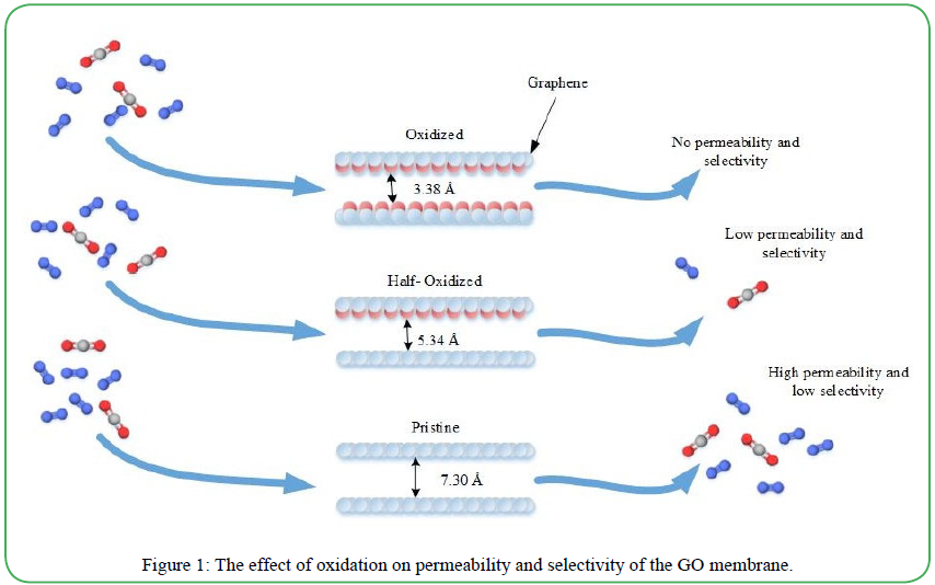
Figure 1: The effect of oxidation on permeability and selectivity of the GO membrane.
It is most common to see post-combustion carbon capture processes in a single-stage process. That is, the CO2 is captured directly from the flue gas with little further processing. It has been shown that a CO2-selective membrane cannot achieve 90% capture and 95% CO2 purity simultaneously within a single-stage separation unit in flue gas from a typical coal-fired plant [55]. A nitrogen-selective membrane can produce a concentrated CO2 stream that exits on the high-pressure side, which could reduce the energy required for compression for long-term storage. Because the flue gas of a typical coal or natural gas combustion plant consists mostly of N2 (70 vol%), there is a higher driving force for separation (i.e., higher partial pressure difference across the membrane). Several studies on polymer-based N2-selective membranes show N2 selectivity over CO2; however, the reported N2/CO2 selectivities were mostly low (below 20). Vanadium has several uses in environmental and energy applications, such as selective catalytic reaction catalysts, electrodes for lithium-ion batteries, hydrogen storage, and fusion systems. This study, conducted by Yuan et al., focused on the vanadium membrane, a type of metallic nitrogen selective membrane. Key steps found in the mechanism of this membrane include catalytic dissociation of N2 into nitrogen atoms on the surface of the membrane and diffusion of nitrogen atoms across the membrane bulk. Solution-diffusion mechanisms have also been experimentally proven to enable the membrane to have N2/CO2 selectivities that are multiple ordersof- magnitude higher than that of polymer-based membranes. One uncertainty that applies to not only the vanadium membrane, but any application of membrane technology for the use of carbon capture, is the effect of minor flue gas components (SOx, NOx, H2O, and O2) on the membrane material. The results from the thermochemical exposure in combination with X-ray photoelectron spectroscopy (XPS), scanning electron microscopy (SEM) and in situ X-ray diffraction (XRD) showed that SO2, NO, and NO2 are not likely to be adsorbed to the surface of the vanadium oxides.
Heat Transfer
Lara et al. used silica as an amino-solid in their model of a 500 MWe coal power plant [56]. The capture plant is modeled as a sorption reactor and a regeneration reactor, where the sorption reactor is a circulating fluidized bed that operates at 42.5°C and 1.3 bar. A main point of interest was the integration of the carbon capture process into the power plant. This would need to be done effectively to avoid a significant energy penalty due to the fraction of fuel that must be dedicated to the carbon capture process for a fixed quantity of work output [57] in the regeneration step, which requires the most energy. In order to conduct this study and to focus on the effects of integration and energy penalties, the sorption capacity was assumed to be 42 mg CO2/g sorbent. Two objectives were defined: providing the energy required for sorbent regeneration while maintaining, in addition, maintaining the flow and final temperature of the product stream. One solution to achieve these objectives is through utilization of internal energy integration. Based on pinch analysis, the required energy for preheating before the sorption reactor and regeneration can be supplied from the energy in the flue gas. A heat exchanger network is then defined to achieve this. The remaining required energy is provided by intermediate pressure steam bleed. Without this integration, the net efficiency of the power plant was calculated to be 38.1%, with an efficiency penalty of 8.8 points. Although this efficiency penalty is not high enough to deem this process infeasible, the heat integration does add definite improvements. With a net efficiency of 39.24%, the heat integration scenario had an efficiency penalty of 7.7. With additional improvements, this could be reduced to 6 efficiency penalty points.
Cryogenic separation is one of the few methods that can effectively capture CO2 without the use of chemicals. However, to achieve the low temperatures needed for separation, immense amounts of energy are required for the cooling duty. Several studies have been completed ways to reduce the energy needed to capture carbon using this method have been completed. Song et al. simulated a cryogenic separation system based on Stirling coolers, followed by an analysis of energy efficiency. The energy consumption of specific stages was evaluated under different operating conditions such as the flow of the gas stream, temperature of the cooler and CO2 concentration. The change in CO2 concentration had the most significant effect on energy consumption, where [58] a variation of 5 to 40% CO2 in the flue gas increased the total energy consumption from 30 to 124 W. Temperature change had the least amount of impact on energy consumption. Specifically, decreasing the temperature of the cooler from -20 to -60°C increased the total energy consumption from 53.73 to 57.41 W
Several notable systems utilizing cryogenic separation have been proposed. Clodic et al. created a cryogenic system that uses a refrigeration cascade for separation [59]. The process required water removal before the CO2 capture stage to avoid issues associated with ice formation. The CO2 is then deposited on the surface of the frosting evaporator as a frost layer, but unfortunately, this decreases efficiency because of the hindered heat transfer. Other systems utilizing packed beds have been able to overcome this problem. These processes can separate both water and CO2 on the packing surface without the need for additional drying stages. Willson et al. proposed a cryogenic process that attempts to reduce energy consumption and overall costs of CO2 separation. Their A3C separation process uses a moving bed of metallic beads both as the heat transfer medium and as the surface to collect the frost to achieve better heat transfer while avoiding the negative effects of heavy frost deposition. The process was shown to be feasible for a range of scales and CO2 concentrations and can be seen in Figure 2 below. After a technoeconomic analysis, a large-scale comparison of an MEA capture showed a similar cost association, while a small-scale comparison showed a significantly lower cost associated with the cryogenic system. It was noted that the results may be skewed by location, since different locations have varying availability and cost of heat, electricity and/or cooling water. Overall, this process provides several advantages over other cryogenic processes, including simplicity and avoidance of gas compression, which makes it a viable alternative for carbon capture.
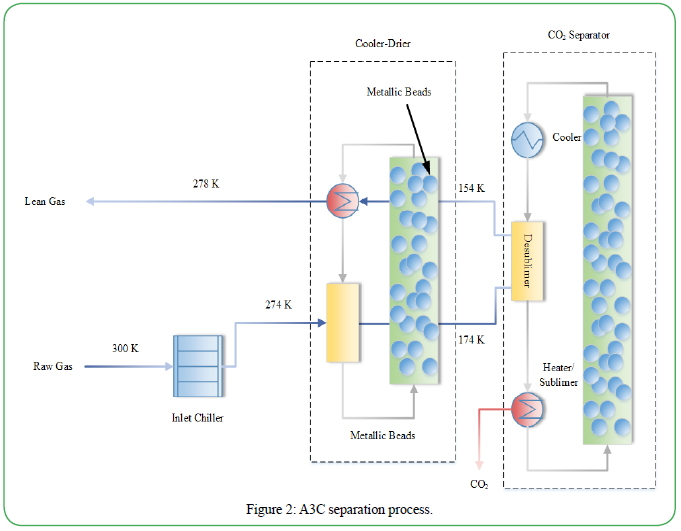
Figure 2: A3C separation process.
Numerous parameters have been studied in desbulimaton processes and it was found that the initial wall temperature has little effect on the desublimation rate, which eliminates the need for precooling before capture [60]. A lower velocity and higher concentration of supplied CO2 will lead to a higher capture rate and lower energy consumption, potentially leading to a different design in which multiple tubes carry CO2 at low velocities to maintain the desired flow and capture rates.
Conclusion
Climate change is a global crisis responsible for several disasters worldwide, such as rising temperatures, rising ocean levels, and greater intensity of droughts and wildfires. Climate change is directly correlated with emissions of GHGs? gases such as CH4, nitrous oxide, and CO2. This causes a greenhouse effect where the gases are trapped in the atmosphere, which raises global temperatures. With emissions of GHGs? gases increasing year-over-year, economical and sustainable solutions must be implemented. Because CO2 is a main contributor to climate change and a major product of combustion, carbon capture could be a viable solution. A technology originally utilized as an oil sweetener is now heavily researched in hopes of reducing the amount of CO2 being released into the atmosphere. The Inter-governmental Panel on Climate Change has recently released their Fifth Assessment Report, which explains the importance of carbon capture to mitigate climate change.Of the climate models that were cited, more than half required carbon capture to economically stay within 2°C of warming compared to the pre-industrial period.
There are several carbon capture methods in varying stages of development, each of which has advantages and disadvantages. The broadest categories include post-combustion, pre-combustion and oxy-fuel capture. Post-combustion capture was the focus of this review paper due to its popularity and relatively simple implementation in fossil fuel-burning facilities, such as power plants and other energyintensive industrial facilities. Post-combustion capture can be further broken down into liquid, solid and miscellaneous methods, such as cryogenic separation. The only method of carbon capture that is currently commercially implemented is organic liquids (MEA and MDEA). MEA does an excellent job of capturing CO2, however, several characteristics suppress its potential. For example, the desorption process requires an immense amount of energy and and MEA is corrosive, both of which increase operational costs. Although MEA is the most mature method for carbon capture, many other methods show promising features and could result in an increase of carbon capture and a decrease in CO2 emissions.
Conflict of interests:
The authors have no conflicts of interest to declare regarding the present manuscript.
References
Carbon Dioxide Emissions From Energy Consumption by Source, in Monthly Energy Review August 2019. 2019: U.S. Energy Information Administration.View
Global Energy & CO2 Status Report. The latest trends in energy and emissions in 2018 2018 [cited 2019 Sep 9th]; Available from: https://www.iea.org/geco/emissions/.View
Projected growth in CO2 emissions driven by countries outside the OECD, EIA, Editor. 2016.View
Durkee, J. US. Global Warming Potential 2006 [cited 2019 Sep 9th]; Available from: https://www.sciencedirect.com/topics/ earth-and-planetary-sciences/global-warming-potential.
Lindsey, R., Climate Change: Atmospheric Carbon Dioxide, N.O.a.A. Administration, Editor. 2019: Climate.gov.View
Fossil fuels still dominate U.S. energy consumption despite recent market share decline. 2016 [cited 2019 Sep 15th]; Available from: https://www.eia.gov/todayinenergy/detail. php?id=26912.View
Hausfather, Z., Common Climate Misconceptions: Atmospheric Carbon Dioxide. Yale Climate Connections.View
Haszeldine, R.S., et al., (2018). Negative emissions technologies and carbon capture and storage to achieve the Paris Agreement commitments. Philosophical Transactions of the Royal Society A: Mathematical, Physical and Engineering Sciences, 376(2119): p. 20160447.View
Lin, A. Carbon Capture and Storage. Innovation 2016 [cited 2019 Sep 9th]; Available from: http://princetoninnovation.org/ magazine/2016/05/11/carbon-capture-storage/.
Carbon capture, utilisation and storage. Capture Sep 23, 2019]; Available from: https://www.iea.org/topics/carbon-capture-andstorage/ capture/.View
Kätelhön, A., et al., (2019). Climate change mitigation potential of carbon capture and utilization in the chemical industry. Proceedings of the National Academy of Sciences, 116(23): p. 11187-11194.View
Carbon Capture. [cited 2019 Sep 9th]; Available from: https:// www.c2es.org/content/carboncapture/.View
Carbon capture, utilisation and storage. Overview Sep 26th, 2019]; Available from: https://www.iea.org/topics/carboncapture- and-storage/.View
Mumford, K.A., et al., (2015). Review of solvent based carbondioxide capture technologies. Frontiers of Chemical Science and Engineering, 9(2): p. 125-141.View
DOW Monoethanolamine. Product Safety Assessment May 15, 2015 Sep 29th, 2019]; Available from: http:// msdssearch.dow.com/PublishedLiteratureDOWCOM/ dh_096d/0901b8038096dabf.pdf?filepath=productsafety/ pdfs/noreg/233-00265.pdf?filepath=productsafety/pdfs/ noreg/233-00265.pdf&fromPage=GetDoc.
Cuccia, L., et al., (2019). Monitoring of the blend monoethanolamine/methyldiethanolamine/water for postcombustion CO2 capture. International Journal of Greenhouse Gas Control, 80: p. 43-53.View
Botheju, D., et al., (2010). Monoethanolamine biodegradation processes. Elsevier. p. 77-86.View
Ma, C., F. Pietrucci, and W. Andreoni (2015). Capture and Release of CO 2 in Monoethanolamine Aqueous Solutions: New Insights from First-Principles Reaction Dynamics. 11(7): p. 3189-3198.View
Hansen, J.-P. and I.R. McDonald, Ionic Liquids. 2006, Elsevier. p. 291-340.View
Aghaie, M., N. Rezaei, and S. Zendehboudi, A systematic review on CO2 capture with ionic liquids: Current status and future prospects. Renewable and Sustainable Energy Reviews, 2018. 96: p. 502-525.View
Samanta, A., et al., Post-Combustion CO2 Capture Using Solid Sorbents: A Review. Industrial & Engineering Chemistry Research. 51(4): p. 1438-1463.View
Drage, T.C., et al., (2012). Materials challenges for the development of solid sorbents for post-combustion carbon capture. J. Mater. Chem., 22(7): p. 2815-2823.View
T.J., T., et al., (2006). CO2 capture systems using amine enhanced solid sorbents.
Ahmed, R., et al., (2020). Recent advances in carbon-based renewable adsorbent for selective carbon dioxide capture and separation-A review. Journal of Cleaner Production, 242: p. 118409.View
Jackson, R.S., (2014). Post-Fermentation Treatments and Related Topics. Elsevier. p. 535-676.View
Rodriquez-Reinoso, F. and J. Silvestre-Albero, Encyclopedia of Materials: Science and Technology. 2 ed. Activated Carbon and Adsorption, ed. K.H.J. Buschow, et al. 2001, Materials Science and Materials Engineering Elsevier.
Sreńscek-Nazzal, J. and K. Kiełbasa, (2019). Advances in modification of commercial activated carbon for enhancement of CO2 capture. Applied Surface Science, 494: p. 137-151.View
Huang, P.-H., H.-H. Cheng, and S.-H. Lin, (2015). Adsorption of Carbon Dioxide onto Activated Carbon Prepared from Coconut Shells. 2015: p. 1-10.View
Ding, M., et al., (2019). Carbon capture and conversion using metal–organic frameworks and MOF-based materials. Chemical Society Reviews, 48(10): p. 2783-2828.View
Sumida, K., et al., (2012). Carbon Dioxide Capture in Metal– Organic Frameworks. Chemical Reviews, 112(2): p. 724-781.View
Daglar, H. and S. Keskin, (2018). Computational Screening of Metal-Organic Frameworks for Membrane-Based CO2/N2/ H2O Separations: Best Materials for Flue Gas Separation. The Journal of Physical Chemistry, 122: p. 17347-17357.View
Didas, S.A., et al., (2015). Amine–Oxide Hybrid Materials for CO2 Capture from Ambient Air. 48(10): p. 2680-2687.View
Madsen, H.T., (2014). Chapter 6 - Membrane Filtration in Water Treatment, in Chemistry of Advanced Environmental Purification Processes of Water, E.G. Sogaard, Editor. Elsevier. p. 199-248.View
Fu, Q., et al., (2013). Highly permeable membrane materials for CO2 capture. Journal of Materials Chemistry A, 1(44): p. 13769.View
Willson, P., et al., (2019). Evaluation of the performance and economic viability of a novel low temperature carbon capture process. International Journal of Greenhouse Gas Control, 86: p. 1-9.View
Mat, N.C. and G.G. Lipscomb. (2019). Global sensitivity analysis for hybrid membrane-cryogenic post combustion carbon capture process. International Journal of Greenhouse Gas Control, 81: p. 157-169.
Hasse, D., et al., CO2 Capture by Cold Membrane Operation. Energy Procedia. 63: p. 186-193.View
Jones, D.A., T. McVey, and S.J. Friedmann (2013). Technoeconomic Evaluation of MEA versus Mixed Amines for CO2 Removal at Near-Commercial Scale at Duke Energy Gibson 3 Plant. Office of Scientific and Technical Information (OSTI).View
UW Professor Leads Research on Reducing Energy Consumption of CO2 Capture. 2018 Oct 5th,2019]; Available from: https://www.uwyo.edu/uw/news/2018/08/uw-professorleads- research-onreducing-energy-consumption-of-co2- capture.html.
Chenxu Li, X.S., Shufeng Shen (2019). Performance Evaluation of Newly Developed Absorbents for Solvent-Based Carbon Dioxide Capture. Energy Fuels, 33(9): p. 9032-9039.View
Lai, Q., et al., (2008). Catalyst-TiO(OH)2 could drastically reduce the energy consumption of CO2 capture. Nature Communications, 9(1).View
Toan, S., et al. (2018). Green, safe, fast, and inexpensive removal of CO2 from aqueous KHCO3 solutions using a nanostructured catalyst TiO(OH)2: A milestone toward truly low-cost CO2 capture that can ease implementation of the Paris Agreement. Nano Energy, 53: p. 508-512.View
Quyn, D., et al. (2013). Results from a Pilot Plant Using Unpromoted Potassium Carbonate for Carbon Capture. Energy Procedia, 37: p. 448-454.View
Endo, K., et al. (2011). A Process for Removing Acid Gases. European Patent Office.
Li, F., et al. (2019). Protic ionic liquids with low viscosity for efficient and reversible capture of carbon dioxide. International Journal of Greenhouse Gas Control, 90: p. 102801.View
Zhang, N., et al. (2019). Highly Efficient and Reversible CO2 Capture by Task-Specific Deep Eutectic Solvents. Industrial & Engineering Chemistry Research, 58(29): p. 13321-13329.View
Asadi-Sangachini, Z., et al., (2019). The feasibility of costeffective manufacturing activated carbon derived from walnut shells for large-scale CO2 capture. Environmental Science and Pollution Research.View
Kaur, B., R.K. Gupta, and H. Bhunia, (2019). Chemically activated nanoporous carbon adsorbents from waste plastic for CO2 capture: Breakthrough adsorption study. Microporous and Mesoporous Materials, 282: p. 146-158.View
Ünveren, E.E., et al., (2017). Solid amine sorbents for CO2 capture by chemical adsorption: A review. Petroleum, 3(1): p. 37-50.View
Gelles, T., et al., (2019). Recent advances in development of amine functionalized adsorbents for CO2 capture. Adsorption.View
Silica, mesostructured. Sigma-Aldrich.View
Zhou, C., et al., (2019). Energy and Economic Analysis for Post-combustion CO2 Capture using Amine- Functionalized Adsorbents in a Temperature Vacuum Swing Process. Energy Fuels, 33: p.1774-1784.
Taheri Qazvini, O. and S.G. Telfer (2019). A Universal Porous Adsorbent for the Selective Capture of Carbon Dioxide. American Chemical Society (ACS).View
Li, W., et al. (2016). Molecular Dynamics Simulations of CO2/ N2 Separation through Two-Dimensional Graphene Oxide Membranes. The Journal of Physical Chemistry, 120: p. 26061- 26066.View
Yuan, M., et al., (2017). Vanadium As a Potential Membrane Material for Carbon Capture: Effects of Minor Flue Gas Species. Environmental Science & Technology, 51(19): p. 11459-11467.View
Lara, Y. and L.M. Romeo (2017). Amine-impregnated Alumina Solid Sorbents for CO2 Capture. Lessons Learned. Energy Procedia, 114: p. 2372-2379.View
House, K.Z., et al. (2009). The energy penalty of postcombustion CO2 capture & storage and its implications for retrofitting the U.S. installed base. 2(2): p. 193.View
Song, C., Y. Kitamura, and S. Li (2014). Energy analysis of the cryogenic CO2 capture process based on Stirling coolers. 65: p. 580-589.View
Clodic, D., M. Younes, and A. Bill, Test results of CO2 capture by anti-sublimation capture efficiency and energy consumption for boiler plants. 2004. II(Proceeding of the 7th International Conferene on Greenhouse Gas Control Technologies 5-September 2004, Vancouver, Canada): p.1775-1780.View
Wang, Y.N., et al., (2018). Transient model of carbon dioxide desublimation from nitrogen-carbon dioxide gas mixture. International Journal of Heat and Mass Transfer, 127: p. 339- 347.View