
- About the Journal
- Editorial Board
- Review Process
- Author Guidelines
- Article Processing Charges
- Special Issues
- Current Issue
- Past Issue
 Current Research in Materials Chemistry
Current Research in Materials Chemistry Volume 4 (2022), Article ID: CRMC-114
https://doi.org/10.33790/crmc1100114Research Article
Ferrites Embedded Nanocomposites for High-Q inductors
N. B. Singh, Thomas Knight*, Fow-Sen Choa, Bradley Arnold, Julian Loiacono and Jennifer Betley
University of Maryland Baltimore County, 1000 Hilltop Circle, Baltimore, MD 21240, United States.
*Northrop Grumman Corporation, ATL, 1212 Winterson Road, Linthicum, MD 21235, United States.
*Corresponding Author Details: N. B. Singh, Professor, Department of Chemistry and Biochemistry, University of Maryland Balti-more County, 1000 Hilltop Circle, Baltimore, MD 21240, United States. E-mail: singna@umbc.edu
Received date: 18th June, 2022
Accepted date: 09th July, 2022
Published date: 11th July, 2022
Citation: Singh, N.B., Knight, T., Choa, F.S., Arnold, B., Loiacono, J., & Betley, J.,(2022). Ferrites Embedded Nanocomposites for High-Q inductors. Cur Res Mater Chem 4(1): 114.
Copyright: ©2022, This is an open-access article distributed under the terms of the Creative Commons Attribution License 4.0, which permits unrestricted use, distribution, and reproduction in any medium, provided the original author and source are credited.Creative Commons Attribution License, which permits unrestricted use, distribution, and reproduction in any medium, provided the original author and source are credited.
Abstract
Polymer matrix based nano ferrite composites were prepared to achieve high inductance and hence to increase the performance of RF devices on chip inductors. A commercially suitable and scalable spin spray method was used to demonstrate the feasibility of deposition on silicon wafer. A detailed studies was performed with three alloys of Fe70Al5Cu5Si20Oδ, Co70Fe9Cu6Si15Oδ, and Co70Al5Fe20Si5Oδ compositions. These composites of ferrite magnetic nanomaterials were fabricated into the ring structures and properties such as permeability and resistivity were measured to correlated with morphology and concentration of the alloy in the matrix. Fabricated single coil coplanar inductors were characterized for the electrical and magnetic properties for the 100 to 100,000 KHz frequency range. The measurement showed performances improvement in the frequency range up to 1000KHz. The Co/Fe nanocomposite sample showed high permeability and a flat response as function of voltage and frequency making it a very good embedded inductor material. These composites provided inductance in the range up to 10 µH a suitable value for practical applications.
Keywords: Inductor; Nanoparticle; Composite; Alloys; Magnetic; Silicate; Coil; Frequency
Introduction
1.1 Background: There is a strong thrust for the electronic systems toward multifunctional and extreme miniaturization at lower costs and higher speed. To achieve these goals, chips require advanced power management. Integration of power supplies with the mixed-signal circuit would enable more coordinated power management, lower chip count, and perhaps less printed-circuit board area, and hence reduces the cost. These goals cannot be achieved without development of novel nanocomposites based light weight, low loss and high-power density inductors. Very exciting and pioneering researches have been performed by Tumala and his team [1-5] in developing ferrite paste. Most of the commercial power circuitry components involve high frequency nickel zinc-based. YIG or other ferrites for inductors. Although these materials have been tested for several designs, the most studied inductors [5-13] are in donut shape. The applications of high-frequency and high-power converters require improvements in the design to miniaturization and development of soft magnetic materials more specifically for systems in the range or over MW power. In many cases, limitation of materials for a design is the road block for theenhancement of the performance in high power and high frequency range.
McHenry and his coworkers [12,13] have discussed a comprehensive design of alloys for magnetic applications. They have used following equations which relates Faraday’s law of induction to the voltage response of an ideal toroidal core with inductance L driven by an AC current:
I = I0sin(ωt) ………...(1)
V= -NA dB/dt ……………(2) = -LdI/dt
= - LI0ωCos(ωt) ……..….(3)
= -µN2A/l . I0ωCos(ωt) …… 4)
Where V is the voltage, µ is permeability, N is number of turns, and l is the effective length, A is the cross-sectional area and is ω the 2πf, f is frequency. To achieve constant maximum voltage, permeability, number of turns, and effective length, the cross-sectional area is inversely proportional to the frequency (ω = 2πf). This relation motivates the use of high-frequency switching to reduce size and weight of passive inductive components in power converters.
Most of the donut shape inductors are generally bulky and occupy a large volume of the power devices and components. Improvements in design, compositions and nano processing provides great potential to match high-power density for the current and upcoming high power wide band-gap semiconductors based systems. Materials which can meet requirements of high frequencies have the potential to greatly reduce the size of power electronics. To accomplish these goals, we have studied cobalt and iron based three alloys Fe70Al5Cu5Si20Oδ, Co70Fe9Cu6Si20Oδ, and Co70Al5Fe20Si5Oδ compositions and characterized properties. Results of these soft magnetic materials involving cobalt, copper, iron, aluminum and silicon is presented in this article.
1.2 Approach to design of materials for high inductance: The materials design was focused to achieve high induction by designing ferrite material, developing high loadings of composites in polymers matrix and evaluate method for commercial production. It is desirable to use low temperature process. Most of the commercial processes involve screen printing on to a ceramic which are sintered at high temperatures and organics are burned off. The left-over composite covers portion of the inductor.
When selecting an inductor, it is important to consider maximum input voltage, output voltage, switching frequency, maximum ripple current and the duty cycle which all depend on materials characteristics. To achieve these parameters, which are responsible for high performance magnetic frequency inductors, one can utilize the quality factor proposed by McHenry et al. The quality factor Q is given as:
Q = ωL/R = µ' / µ''
Where µ' and µ'' are the real and imaginary parts of complex permeability is a performance measure for an inductor. It is observed that generally high permeability materials saturate under low fields. The quality factor does not consider the magnetic saturation which is important for high power applications in addition to the amount of energy stored and the losses in the material. There are several ways to define the merit of materials. For practical purposes ratio of the stored power and power loss is a good measure for the suitability of material. To achieve high inductance material, we used as -suppled nano materials and prepared in-house followed by embodiment in the matrix. We used several approaches of embodiment of nanoparticles in polymeric materials including spin spray on silicon and sapphire substrates to achieve very thick film.
2. Experimental Method and Results
2.1 Materials and Synthesis: Our attempt was to perform experiments with multinary compositions of alloys with high loadings in polymers. However, very high loadings caused fracturing of samples during preparation of shaped inductors. Reactive aqueous solution methods have been used for cobalt (Co) and iron (Fe) based nanocomposites by preparing the starting precursors, co-atomization of the precursors to form colloidal solution followed by annealing to form the nanocomposite powders. However, this requires longer time for optimization. We took a simpler approach in which we took nano and micro particles of constituting elements. The particles sizes were in the range of 50 -200 nm. To obtain uniformity of nanoparticle, as supplied materials were combined and placed into the Wig-L-Bug and used a time of 10 -15 minutes for grinding and mixing. For the embodiment of the nanoparticles we will use the commercially available polymers and epoxies with low loss characteristics. Following compositions of alloys were prepared by mixing the oxides:
1. Fe70Al5Cu5Si20Oδ
2. Co70Alfa2ₒSi5Oδ
3. Co70Fe9Cu6Si15Oδ
We used cobalt and iron based alloys and varied the amount of silicon significantly to evaluate its effect. The binding chemicals used in making composites were PMMA, Cyclohexane and Isopropanol.
2.2 Preparation of Composites: We evaluated two methods which are suitable for commercial production.
2.2(a) Annealing and curing in solvent: This method involved wet chemistry and the control of oxygen was very difficult. Alloys particles were mixed in desired ratio to achieve compositions:
Fe70Al5Cu5Si20Oδ, Co70Al5Fe2ₒSi5Oδ and Co70Fe9Cu6Si15Oδ. We used as supplied commercially available PMMA and other chemicals for the matrix. In the beginning of the study we used test experiments with several compositions of the components, evaluated annealing temperature and curing time for preparing the composites. Most of the test experiments were performed with smaller amount. A typical run involved 1g of each component. For these alloys the compositions and optimum conditions for the fabricable composite are listed in Table 1.
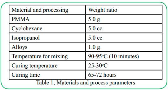
Table 1; Materials and process parameters
When we tried higher loadings in the range of 5g for parameters listed in Table 1, the fracturing and stresses in the composite increased significantly. As the composite cured, it started breaking and twisting as shown Figure 1.
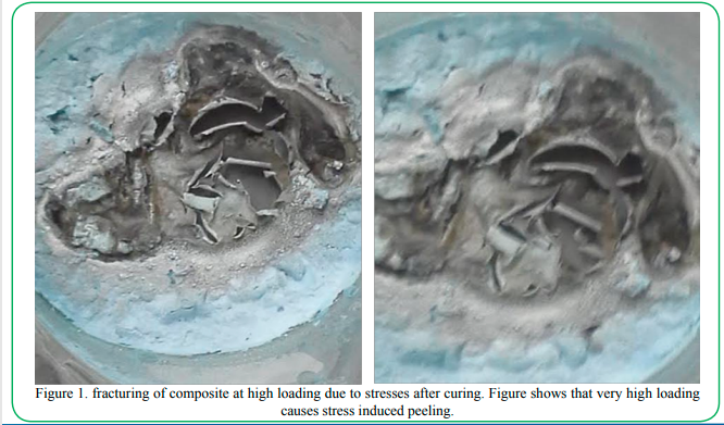
Figure 1. fracturing of composite at high loading due to stresses after curing. Figure shows that very high loading causes stress induced peeling.
2.2 Spin spray method: We evaluated the spin spray method also. This method involved preparation of a salt solution that contains Co, Fe, Si, Cu and Al with the desired atomic ratio. In order to dissolve the oxides, we used dilute nitric acid. In some case few drops of HCl was also required. We used NH4OH solution into the precursor solution to control pH, and to convert the precursor solution into a complex powder. Solution was heated up to 50C to ensure the complete mixing. This is an easier method especially when we use low loading of the materials. As the loading increases, the hardness of the material increased causing fracturing of the composite. To achieve the uniformity of the composite by this method we had to decrease the viscosity by adding excess of cyclohexanol and isopropanol. This required longer time to cure the material. This test was performed on silicon wafer to evaluate the feasibility.
In a typical run for spin spray we used 10g of PMMA, 0.2g of the nanoparticles, 12.5 microliters of DBP, .5ml of Cyclohexane and.5ml of isopropanol. We Stirred the mixture with a glass rod and place a small glass vial in the center of the mixture to pour the material for spin spray for deposition on wafers. The microstructure of the film is shown in Figure. The toroid shape inductor fabrication involved cutting or peeling of the film followed by copper wire wrapping on the material.
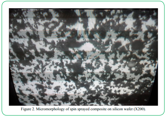
Figure 2. Micromorphology of spin sprayed composite on silicon wafer (X200).
2.3 Inductor Fabrication: To perform low frequency permeability measurements, the as-formed pastes were poured into a mold. The cast pastes were then cured at 90C for 8 h to allow for hardening to form donut-type toroid. A typical photograph of cured toroid is shown in Figure 3. The formed toroid was then winded with magnetic wires for the inductance and permeability measurement.
Figure 3. Typical toroid (a) without and (b) with copper wire prepared by using composite of material in this study
As casted toroids made of different compositions were wrapped with copper wire. The typical parameters for the wire were:
• Length of wire: 4ft • Wraps: 100 Wraps • Diameter: 30 Gauge
2.4 Measurements:
The preliminary measurements were performed using multimeter and utilized an impulse machine to determine inductance. The details of electrical measurements were made by using a LCR meter. We had made a special holder to use the sample so that there were no inconsistencies in the measurements. The measurements were determined for the frequency range of 100 Hz to 100,000Hz. Also determine the effect of voltage we used a range of 50mV to 1000mV range. Table 2 summarizes the measured inductance at different frequency and voltage. For the measured range of voltage (Figure 4) and frequency, there was no variation in the value of inductance.
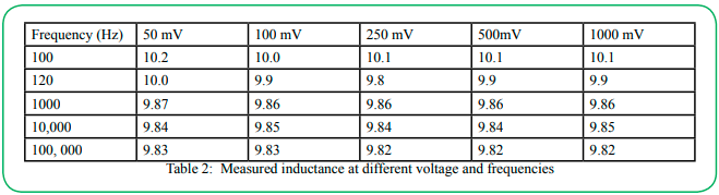
Table 2: Measured inductance at different voltage and frequencies
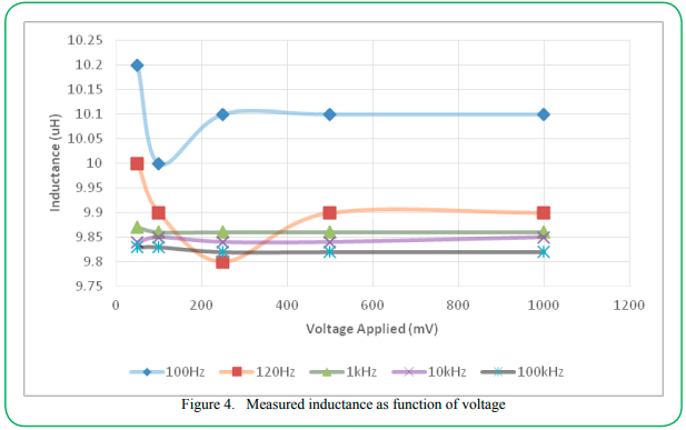
Figure 4. Measured inductance as function of voltage
Permeability µ can be measured from inductance in a toroid. A simplified equation for inductance can be given as:
L = µN2A/2πr
Where A is the cross-section area, N is number of turns of wire and r is the toroid radius to centerline. Inductance is much easier to measure directly, so we will determine permeability with the above relation. Figure 4 shows the measured data at different voltage and frequency. We observed that inductance was almost constant and did not change with voltage and frequency in the MHz range.
The permeability was determined by using following equations;
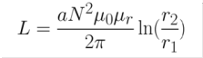
Figure 7.
Where L is inductance in Henry, a is height in meters, N is number of turns of wire, μ0 is permeability of free space, μr relative permeability, r2 is outer radius in meters, r1 is inner radius in meters. Solving for µr:
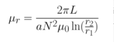
Figure 8.
Based on this equation the permeability for samples were; Sample Co70Al5Fe20Si5Oδ= (2πι10e-6)/(3e-3.1002.1) =2.087 in MHz range
Sample Co70Fe9Cu6Si15Oδ = (2.π.3e-6)/(2e-3*1002.1) =1.446 in MHz range
The values for the sample Fe70Al5Cu5Si20Oδ, were also in the range of 1.4 in the MHz range. The value of permeability is independent of frequency.
3. Summary
Nanoparticles of Fe70Al5Cu5Si20Oδ, Co70Fe9Cu6Si15Oδ, and Co70Al5Fe20Si5Oδ ferrites were embedded in polymer matrix to prepare composites. These composites of ferrite magnetic nanomaterials were fabricated into the ring structures and to measure properties such as induction and permeability to correlated with morphology and concentration of the alloy in the matrix. We demonstrated synthesis of bulk and spin sprayed thick film of the composite. High concentration loading showed tresses and peeling from the substrate. Fabricated single coil coplanar inductors were characterized for the electrical and magnetic properties of these materials at 100 to 100,000 KHz range. This novel composite demonstrated inductance in the range of 10 µH. The derived values of permeability were in the range of 1.5 to 2.1 for the MHz frequency range. Also, the inductance for this nanocomposite was independent of frequency and voltage in measured range.
Acknowledgements
This project was supported by the Northrop Grumman Corporation as enterprise student design project. We are grateful to Ms. Veronica Nelson for her support and encouragements.
Conflict of interest:
The authors declare no conflict of interest.
References
K. P. Murali, Himani Sharma, Raj Markondeya Pulugurtha and Rao Tumala, (2015). Journal of Materials in Electronics 27(1) 154.View
D. Xiao, X.Q. Ma, H. Zhang, D.E. Reisner, P.M. Raj, L. Wan, and R. Tummala, (2005). "Magnetic Nanocomposite Paste: An Ideal High- µ, k and Q Nanomaterial for Embedded Inductors in High Frequency Electronic Appls.," Procs. 9th World Multiconference on Systemics, Cybernetics and Informatics, July 10-13, Orlando, FL.
H. Lee, B. S. Cook, K. P. Murali, Markonday Raj, Mano Tentzeris, (2016). IEEE Microwave and Wireless Components Letters, 26, 6 ,419.View
Y. D. Zhang, S. H. Wang, D. T. Xiao, J. I. Budnick, and W. A. Hines, (2001). “Nanocomposite Co/SiO2 soft magnetic nanomaterials”, IEEE Trans. Magnetics, Vol. 37, no. 4, 2275.
Y.D. Zhang, S. Wang, and T.D. Xiao, (2004). "Insulator coated magnetic nanoparticulate composites with reduced core loss and method of mfg thereof," US Patent No. 6,720,074 B2.
Y. Yoshizawa, S. Oguma, and K. Yamauchi, (1988). J. Appl. Phys. 64, 6044.View
H. Fukunaga, T. Eguchi, K. Koga, Y. Ohta, and H. Kakehashi, (1990). IEEE Trans. Magn. 26, 2008.View
T. Yanai, K. Takagi, K. Takahashi, M. Nakano, Y. Yoshizawa, and H. Fukunaga, (2008), J. Magnetism and Magn. Mater. 320, 20, 833.View
H. Fukunaga, T. Yanai, H. Tanaka, M. Nakano, K. Takahashi, Y. Yoshizawa, K. Ishiyama, and K.I. Arai, (2002). IEEE Trans. Magn. 38, 3138.View
Y. Yoshizawa, S. Fujii, D.H. Ping, M. Ohnuma, and K. Hono, (2003). Scr. Mater. 48, 863.View
J. Zhang, J.-S. Lai, R.-Y. Kim, and W. Yu, (2007). IEEE Trans. Power Electron. 22, 1145.View
J. Long, M. McHenry, D.P. Urciuoli, V. Keylin, J. Huth, and T.E. Salem, (2008). J. Appl. Phys. 103, 07, 07E705. View
Alex M. Leary, Paul R. Ohodnicki, and Michael E. McHenry, (2012). Journal of Metals, 64(7) 772.View